Download
1 / 18
180 likes | 322 Vues
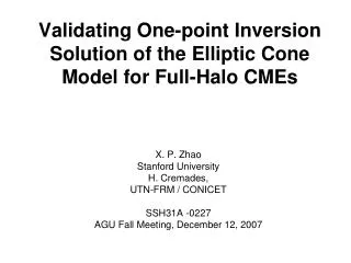
Validating One-point Inversion Solution of the Elliptic Cone Model for Full-Halo CMEs. X. P. Zhao Stanford University H. Cremades, UTN-FRM / CONICET SSH31A -0227 AGU Fall Meeting, December 12, 2007. Abstract

E N D
Validating One-point Inversion Solution of the Elliptic Cone Model for Full-Halo CMEs X. P. Zhao Stanford University H. Cremades, UTN-FRM / CONICET SSH31A -0227 AGU Fall Meeting, December 12, 2007
Abstract By using the elliptic cone model as a geometrical proxy of CME flux ropes, we have established an one-point approach to invert geometrical properties of front side, disk full-halo CMEs, such as the CME propagation direction, shape and angular widths. This work presents an algorithm for determining the radial speed and acceleration of full-halo CMEs on the basis of apparent speed and acceleration measured on the plane of the sky. It is found that by using the one-point approach more than one set of model parameters can be inverted, and all sets can be used to well reproduce observed CME halos. This work attempts to find a way to obtain the valid solution among all inverted sets of model parameters.
1. Introduction • Recent study shows evidence that all single CMEs are hollow flux ropes with two ends anchored at solar surface [Krall, Ap. J., 2007]. • The geometry of the CME flux ropes can be approximated by cones with elliptic cone bases. Most of halo CMEs can be reproduced by projecting the elliptic bases onto the sky-plane [Cremades & Bothmer, 2005; Zhao, 2005]. • We have developed an one-point approach for inverting elliptic cone model parameters [Zhao, 2007]. This poster studies how to find out the optimum inversion solution among many possible solutions.
2. Characteristics of full halo CMEs Zh Zh The center, semi-axes and orientation of 2-D CME halos may be characterized by halo parameters (Dse, α); (Saxh, Sayh); ψ. These 5 parameters contain the information of 3-D CME flux ropes. In addition, the apparent speed & acceleration measured on the sky-plane provide information of the kinematic properties of CMEs. How to invert the CME propagation direction and flux rope parameters from the 5 observed halo parameters? How to invert the radial propagation speed and acceleration from the apparent ones? Yc’ Yc’ SAyh SAyh Ψ ψ Yh Dse Dse Yh α α Xc’ SAxh Xc’ SAxh Fig1. Definition of five halo parameters, Dse, α, Saxh, Sayh, ψ. The white ellipse is determined using 5 points (‘+’) method (Cremades, 2005). Shown at the top are the values of the five halo parameters (Dse, SAxh & SAyh are in solar radii).
3. The elliptic cone model 3.1 Model parameters, (Rc, β, α), (ωy, ωz), χ, denote, respectively, the position, size and shape, and the orientation of the cone base. Ze Zc Xe, Xc (α, β) Xe, Xc (φ, λ) Semi-minor axis Semi-major axis χ Rc Yc Rc Cone base ωy Ye Xe,Xc ωz Cone apex Sun’s center Ye Ze Fig. 2 Definition of model parameters, Rc, ωy, ωz, χin the elliptic base and cone coor. systems XeYeZe and XcYcZc
3.2 Parameters(α, β) or (φ, λ) denote the direction of central axis (propagation) or the source location of CMEs in the Heliocentric Ecliptic Coordinate System XhYhZh. Here themodel parameter αis the same as the halo parameterα. Zh Xc’ Xc Yh Rc α Relationship between β, α and λ, φ sinλ = cosβ sinα (1.1) tanφ = cosα / tanβ (1.2) sinβ = cosλ cosφ (1.3) tanα = tanλ / sinφ (1.4) β λ φ Xh Fig. 3 Definition of propagation direction Xc, i.e., β, α or λ, φ in the Heliocentric Ecliptic coordinate system XhYhZh.
3.3. Relationship between model and halo parameters Rc = Dse / cos β (2.1) tan ωy = {-(a - c sinβ )+[(a + c sinβ )^2+ 4 sinβ b^2)]^0.5} / 2Rc sinβ (2.2) tanχ = (Rc tan ωy - c) / b (2.3) tan ωz = -(a + b tanχ ) / Rc sinβ (2.4) where a = SAxh cos^2 ψ -SAyh sin^2 ψ (3.1) b = (SAhx + SAyh)sinψ cosψ (3.2) c = -SAxh sin^2 ψ+ SAyh cos^2 ψ (3.3) Rc, ωy, χ, & ωz can be calculated using Dse, ψ, SAxh, Sayh if β can be specified. How to determine βusing halo parameter α ?
4. Determination of β using one-point .. Equations (1.1), (1.2) show that α contains information of (λ,φ) . The dotted curve in Fig. 4 corresponds toα = 56.46. All possible β are located on the curve. CME source is believed to be located near the associated flare or filament disappearance. The dot fe is the location of associated flare. The red dot, ‘me’, with shortest distance from fe is one possible β. The blue and green dots, ‘le’, ‘re’, denote two extreme β. Which one is the optimum β ? Flare β α=56.45 Fig. 4 Find out the optimum β on the basis of the location of the flare (the black dot) associated with the 12/13/2006 halo-CME
BlueRedGreen α 56.4° 56.4° 56.4° β 83.6° 72.3° 52.5° ωy 19.8° 44.5° 63.1° ωz 17.6° 42.1° 65.3° Χ 6.6° 6.8° 7.4° Rc(025404) 12.28 4.50 2.25 Vc in km/s 4210 1538 757 Ac in km/s2 -0.146 -0.053 -0.026 Rc(030606) 16.60 6.08 3.30 Rc(034204) 28.85 10.56 5.23 Rc(041804) 40.13 14.68 7.26 ωy, ωz are too small and Rc is too large for Blue cone to produce such bright halo CMEs Fig. 5 The three sets of inverted model parameters are shown on the right (Rc in solar radii). The blue, red, and green dotted ellipses are reproduced using the 3 sets of model parameters. All three ellipses agree well with observed white ellipse, though the model parameters for blue case may not be reasonable.
5. Determination of kinematical properties The sky-plane speed & acceleration, Vsp, and Asp, are measured at a given position angle, PA. For the 2006.12.13_02:54:04 halo, Vsp=1773.7 km/s and Asp=-0.0614 km/s^2 at PA=193°. It may be used to get the radial speed and acceleration at that position angle, Ve, Ae for base edge and Vc, Ac for base center as follows: Vc=Vsp / √(d^2 + e^2) & Ac=Asp / √(d^2 + e^2) (4) Ve=Vc f & Ae=Ac f (5) Where d=cosβcosα+(sinβsinχcosα+cosχsinα)tanωycosδ - - (sinβcosχcosα-sinχsinα)tanωzsinδ (6.1)
e=- cosβsinα-(sinβsinχsinα-cosχcosα)tanωycosδ + + (sinβcosχsinα+sinχcosα)tanωzsinδ (6.2) f = √(1+tan^2 ωycos^2 δ+tan^2 ωzsin^2 δ) (6.3) δ=PA+α-ψ+χ. (6.4) Using calculated Vc, Ac, & the time difference between a later halo and the halo at 02:54:04, the value of Rc can be calculated (see Fig. 5). The blue, red and green ellipses in Figures 6, 7, & 8 show the reproduced halos at 03:06:06, 03:42:04,& 04:18:04 . All ellipses agree with observed halos very well. Therefore, it is not possible to find out the optimum solution by comparing calculated with observed halo.
Fig.6 Based on Vc and Ac, and time difference, we obtain three Rc for the 2006.12.13_03:06:06 halo.The blue, red, and green ellipses are obtained using these values of Rc and other model parameters. Although all agree with observed halo pretty well, the parameter Vc & Rc are too large for blue and too small for green .
6. Comparison with near-surface features The three-part structure in cone-like limb CMEs implies that all low-corona features associated with CMEs, such as flare, SFD, dimming, post-eruption arcade, should occur within cones. The solar disk projection of a cone base that intersects with photosphere should cover all associated features. This inference may be used to determine which β should be selected among many possible β values. The three solid ellipses in Fig. 9 are calculated using the three sets of α, β, ωy, ωz, Χ for 025404 halo shown in Fig. 4 and Rc=cos ωy. The blue one is too small to cover bright features, and the red & green ones cover coronal holes that should occur outside cones. The different mean angular widths (37°, 47° and 72°) among data sets of MK3, SMM and LASCO suggests that some CMEs originated in and near active regions may expand in the early stages of their formation and propagation (Dere et al., 1997; Hudson et al., 2007). Thus, angular widths in low corona may be less than in corona. The dashed ellipses in Fig. 9 are obtained by assuming that the angular width at solar surface is 0.75 of its coronal value. Fig. 9 shows that all bright features are located within only the red dashed ellipse, and all coronal holes are located outside only the red dashed ellipse. The red solution may be the optimum one.
Fig. 9 EIT_195 image showing near-surface features, say, flare and coronal holes. The blue, red and green solid (dashed) ellipses are calculated using ωy (0.75 ωy) and other cone parameters. The dashed red ellipse appears to be the optimum solution.
7. Summary & Discussion • By combining the halo parameter α and the location of associated flare, more than one β value, and more than one set of model parameters, can be inverted. Although some of model parameters are obviously not reasonable, all three sets we tested can still be used to reproduce observed CME halo pretty well (Fig. 5). • By determining the radial CME propagation speed and acceleration on the basis of the measured apparent (sky-plane) speed and acceleration, the observed CME halos at later times can also be well reproduced using these sets of model parameters (Fig. 6, 7, 8). • It shows that the capability of reproducing CME halos is not a strong argument for the validation of the inverted 6 model parameters.
The three-part structure occurred in cone-like limb CMEs implies that all CME-associated low-corona features should be located within an ellipse that is the solar disk projection of the cone base at solar surface. For the event tested here, it can be used to determine the optimum β and other model parameters. More samples are needed to be tested. The two-point approach can be used to further confirm the result. • It should be noted that the inversion solution is valid only for disk frontside full halo CMEs, i.e., for β greater than 45° [Zhao, 2007]. • Reliable determination of halo parameters, especially α, is the key for successfully using the elliptic cone model.