M7100 System Mobile Radio User’s Guide for York County, PA Emergency Services
380 likes | 964 Vues
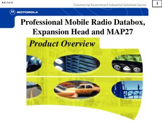
M7100 System Mobile Radio User’s Guide for York County, PA Emergency Services. Training Session Notes. Introducing the M7100. The M7100 is multi-mode mobile radio designed to operate in a challenging public safety environment. We will learn about its operation by: Discussing the RF system.

M7100 System Mobile Radio User’s Guide for York County, PA Emergency Services
E N D
Presentation Transcript
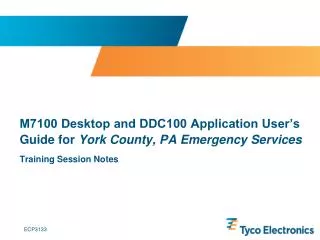
M7100 System Mobile Radio User’s Guide for York County, PA Emergency Services Training Session Notes
Introducing the M7100 • The M7100 is multi-mode mobile radio designed to operate in a challenging public safety environment. • We will learn about its operation by: • Discussing the RF system. • Learning about the parts of the mobile installation. • Name the parts of the control unit. • Originate and receive calls. • Change user parameters. • Become aware of limitations.
Project 25 (P25) • Project 25 is a public safety communications standard dedicated to ensuring interoperability in communications. It is designed to ensure fast and secure communications between local, state and federal agencies when protecting the public's welfare. • The Project 25 standard organization is comprised of the Association of Public Safety Communications Officials (APCO), the National Association of State Telecommunications Directors (NASTD) and the U.S. Federal Government. • The Federal Government through the National Telecommunications and Information Administration (NTIA) has dictated that all new and existing federal communications systems will be P25 compliant. • P25 is an all digital voice system that can be trunking or conventional non-trunking.
Group B Group D Group D Conventional vs. Trunked Trunked Approach Conventional Approach Channel 1 Channel 2 Group C Group A Group C Group A Group B Users Select which Repeater to Use System Selects which Repeater to Use
Why Trunking? • Trunking: • Improves spectral efficiency • Relieves the user from managing the channel • Encourages cross agency / shared communications • Establishes communications privacy • Encourages private communications • Discourages eavesdropping by scanners • Establishes “queuing” rather than “waiting” • Enables priority use during busy times
P25 Trunking System Features • Digital Control Channel • Multiple Working Channels • < 0.5 Second Access • Group & Individual Voice Calls • Unit ID for each radio • Late / Delayed Entry • Emergency Calls • Queuing with Priority • Unit Enable / Disable • Wide Area Coverage
How Far Does it Cover ? • Many factors affect range: • Site Location • Urban Clutter • Reflections / Multipath • Ducting over Water • Heavy vegetation • Weather • Frequency ???
Simulcast – Extending the Coverage • SIMULtaneous broadCAST • All RF sites have: • Same number of channels • Same radio frequencies • Same channel designated as control channel • When someone makes a call, that call is rebroadcast to every site regardless of whether or not someone is there to listen. • The users have no indication that simulcasting is occurring other than better coverage.
Multisite – Extending Coverage • Units inform the network of their location: • Each time the Radio is powered up. • Each time a System selection is made. • Each time a Group selection is made. • When Radio detects a high bit error rate on the Control Channel • Radio will look for another site using an algorithm. • Automatically switches to new site when criteria is met. RF Site 2 RF Site 1
Radio Nomenclature • Before actually operating the radio, one should know some of the terms and descriptions associated with operation. Such as: • Radio • Microphone • Speaker • Control Unit • Display • Buttons • Knobs • Antenna • Let’s take a look at these before actually operating the radio.
Mounting • The M7100 has several mounting configurations that could apply to you. • Front Mount – radio and control is mounted together near the operator. • Remote Mount – the radio is mounted remotely (trunk) and the control unit is near the operator. • Dual Control – Two control units controlling one radio. • Operation is using the control unit.
Operator Position • Control Unit has most of the controls for the radio. • The removable microphone provides voice input as well as the Push To Talk switch. • Speaker is located near the control unit. • Programming or mobile data connector may be visible. Speaker Programming Interface May not be installed! Military Style Microphone
Microphone Microphone Hang-Up-Button PTT • Contains • Microphone – Hold the microphone approximately three inches from the mouth and speak in a normal voice. • PTT – Push-To-Talk and Release-To-Listen • Hang-Up Button – Off hook is the same as a CLEAR/MONITOR function. Placing the microphone on hook will end special calls. (Does not stops scanning.)
CENTRAL EMS MAIN SYS GRP OPT MENU STS MSG CLR SCAN PHN DIS IND Control Unit Display 2 lines 8 characters Power On-Off Volume Control Keypad Indicators Light Sensor Group / Channel Selector 360 Rotation Emergency Scan Add/Delete Ramp Systems Menus Scan On-Off Microphone Connector
LINE 1: System Name (example: CENTRAL) Volume Level (VOL = 10) Caller Identification (GR 1234) ‘Who Has Called’ (* WHC *) Menu (MENU) LINE 2: Talkgroup or Channel Name (EMS MAIN) Call Queued (QUEUED) System Busy (SYS BUSY) Call Denied (DENIED) Individual Call (*INDV*) Control Channel Scan (CC SCAN) Wide Area Scan (WA SCAN) Receive Emergency (*RXEMER*) Transmit Emergency (*TXEMER*) Menu Items (BCK LGHT) Display Messages • Listing of some messages that appear on line 1 and 2.
Basic Operation • Items to Discuss • Power on the radio. • Read the display. • Change systems. • Change groups. • Originate a group call. • Receive a group call. • Declaring an Emergency. • Scanning • Menu Operation
POWER UP SELFTEST SYS GRP OPT MENU STS MSG CLR SCAN PHN DIS IND Power On and Log In • Rotate Volume On/Off Control Clockwise about ¼ turn. • All segments of the VFD* display should briefly display and the display should show Power Up Self Test, followed by an audible beep and the system/group display. • The radio will transmit into the network and log in automatically, telling the network the ID of the radio and the group that is selected. Power On/Off & Volume * Vacuum Florescent Display
CENTRAL EMS MAIN SCAN Displaying the Systems and Groups • The radio’s display is showing the system and group that you are part of. • The top line will be the system name representing a location and a set of groups. Examples are: • NORTH • WEST • CENTRAL • SOUTH • FULTON • UTAC • The second line will show the selected group control by the small buttons on the side of the radio. Examples are: • MAIN • CF ADMIN • CAR CAR1 • EMS MAIN • UCALL 40 • etc
CENTRAL EMS MAIN SCAN Changing the System • The System represents a location and a set of groups. • System names appear on Line 1 of the display. • Press the ramp button up to ramp up to the desired System or down to ramp down to the desired System. 1 In normal operation, the system name may change as the radio acquires the best RF site for operation. The radio will not select the FULTON or UTAC system automatically. 2
CENTRAL EMS MAIN SCAN Changing Groups • A group represents the people to which you want to communicate. • The Group name will appear on Line 2 of the display. • Use the rotary knob on the bottom left to select the group. Rotate the knob in one direction to advance through the list or rotate the knob in the other direction to back up in the list. • The groups are the same in all of your systems except for UTAC. 1 There are lots of groups to select! 2
CENTRAL EMS MAIN SCAN Originate a Group Call • Turn on the radio. • Select the group you want to talk to. • Group names appear on Line 2 of the display. • Push-to-Talk (PTT). • Indicator will light red while transmitting. • Speak into the microphone. 1 4 5 3 6 2
GR 12345 EMS MAIN SCAN Receiving A Group Call • The caller’s Radio ID or alias appears on Line 1 (ex. 12345). • The group that is being received appears on Line 2. • The Indicator will light green while receiving. • Adjust Power On/Off & Volume control for pleasing level of audio, but not to overdrive the speaker. • PTT to respond. 4 1 5 2 3
CENTRAL *TXEMER* SYS GRP OPT MENU STS MSG CLR SCAN PHN DIS IND Declaring an Emergency • Press and hold the red EMERGENCY button for approximately 1 seconds. • *TXEMER* appears in the display and will continue to flash, alternating with the selected group, until the emergency is cleared. • PTT and talk. 3 2 1 Receive Indication • The console dispatcher clears emergencies. • If you declare an emergency, your radio will remain on the group until the emergency is cleared. • This feature only available when in the trunked mode, not available in UTAC system. EM 12345 *RXEMER*
Group Scanning • A list of groups to scan must exist before scanning can occur. • The M7100 System model radio is configured for user programmable scanning – the user creates and modifies the list. • There are three levels of priority. Priority 1 is the highest and priority 3 (S) is the lowest. • Scanning must be off to create, add or delete groups from the scan list.
CENTRAL EMS MAIN SYS GRP OPT MENU STS MSG CLR SCAN PHN DIS IND Turning SCAN On/Off • Press SCAN and release to turn on the scan function; any group in the scan list will be scanned. • The light above the SCAN key indicates SCAN on/off. • Press SCAN again to turn off the scan function (light off). 2 1 & 3 Note: The microphone does not have to be on hook for the scanning to function.
S EMS MAIN SYS GRP OPT MENU STS MSG CLR SCAN PHN DIS IND Establishing or Modifying a Scan List • Make sure Scan is turned OFF. • Select the group you wish to scan. • Press scan ramp up (+) to add the group to the scan list • S,1, or 2 will appear based on user’s desired priority level. • Press scan ramp down (-) to decrease delete the group from the Scan List. 1 3, 4 &5 2
CENTRAL EMS4 SYS GRP OPT MENU STS MSG CLR SCAN PHN DIS IND Nuisance Deleting from a Scan List • User entered or limited scan list only: • When a call is being heard while in scan mode and the call is not the selected or priority 1 group and you wish to remove the group from the scan list. • Press the +/- button down once to show the priority level. Press the button down again to delete the group from the Scan List. • The group or channel will return to the scan list when the radio is powered off and back on. +/-
BCKL 5 EMS MAIN SYS GRP OPT MENU STS MSG CLR SCAN PHN DIS IND Backlight Control • Press DIS button to adjust the brightness of the display, indicators and the backlighting of the buttons simultaneously. • The top line of the display with the current setting (BCKL 1, 2, 3, 4, 5, or 6). • Use the RAMP CONTROL to change the level of brightness from off to 6 (seven levels). • Press the MENU button to accept the value. • If the display is set to off, powering the radio off and back on will power up the radio to display of 1. 2 Ambient light changes will cause the brightness to increase 1 level with bright light or decrease 1 level in darkness, provided the BCKL is not set to the limits of 1 or 6. There is a four second delay. 4 3 1
MENU KEY LOAD SYS GRP OPT MENU STS MSG CLR SCAN PHN DIS IND Menu Control • Press MENU to enter the Menu mode. • The display will show MENU on the top line and the menu item on the second line. • Use the Ramp control to find and select desired menu item, and press M a second time to select the item. • The menu items sub-menu will appear. Again use the ramp control to select the desired choice and press the M button to enter the choice. • Pressing the CLR button will exit the menu without changes or wait for time out (10 seconds) to leave the menu. 2 • Some menu items may exist for maintenance information. While no harm will occur from accessing them, they will not be explained to the user. 1 & 4 5 3 1
Dual Control • Dual Control allows two different control units to control the radio at different times.
Dual Control Operation • Dual Control operation is confirmed when the inactive control unit shows *DUAL* on its display. The active control unit is in control of the radio. • Taking over the control from the active control unit is done by meeting certain requirements at the inactive control unit. • Operating PTT momentarily. (Pressing and releasing the PTT on the microphone is the most common method, but momentarily operation of any PTT function that in programmed in the radio such as Auxiliary inputs will accomplish the transfer.) • Pressing the “Emergency” button, if configured. • Turning off the active control unit will transfer operation to the other control unit. *DUAL* SYS GRP OPT MENU STS MSG CLR SCAN PHN DIS IND
Explosive Atmospheres – Just as it is dangerous to fuel a vehicle with the motor running, similar hazards exist when operating a mobile radio. Be sure to turn the radio off while fueling a vehicle. Do not carry containers of fuel in the trunk of a vehicle if the radio is mounted in the trunk. Areas with potentially explosive atmosphere are often, but not always, clearly marked. Turn OFF your radio when in any area with a potentially explosive atmosphere. It is rare, but not impossible that the radio or its accessories could generate sparks. Interference to Vehicular Electronics Systems – Electronic fuel injection systems, electronic anti-skid braking systems, electronic cruise control systems, etc., are typical electronic systems that can malfunction due to the lack of protection from radio frequency energy present when transmitting. If the vehicle contains such equipment, consult the dealer and enlist their aid in determining the expected performance of electronic circuits when the radio is transmitting. Electric Blasting Caps – To prevent accidental detonation of electric blasting caps, DO NOT use two-way radios within 1000 feet of blasting operations. Always obey the “Turn Off Two-Way Radios” signs posted where electric blasting caps are being used. (OSHA Standard: 1926-900) Liquefied Petroleum (LP) Gas Powered Vehicles – Mobile radio installations in vehicles powered by liquefied petroleum gas with the LP gas container in the trunk or other sealed-off space within the interior of the vehicle must conform to the National Fire Protection Association standard NFPA 58 requiring: The LP gas container and its fittings. Outside filling connections shall be used for the LP gas container. The LP gas container shall be vented to the outside of the vehicle. Transmitter Hazards
RF Energy Exposure Awareness • RF Energy Exposure Information is printed in the operators manual. • The user is expected to read and be aware of this information. • The antenna should be installed on the outside of the vehicle in such a way to minimize RF exposure to the driver and passengers. • Keep away from the antenna when transmitting and report any missing or loose antennas or cables. • For bystanders unaware of the transmitter, a save distance for your band and power would be approximately 3 feet. The distance is less (half) when you are aware of the transmitter and can govern your actions.
Safe Driving Recommendations • (Recommended by AAA) • Read the literature on the safe operation of the radio. • Keep both hands on the steering wheel and the microphone in its hanger whenever the vehicle is in motion. • Place calls only when the vehicle is stopped. • When talking from a moving vehicle is unavoidable, drive in the slower lane. Keep conversations brief. • If a conversation requires taking notes or complex thought, stop the vehicle in a safe place and continue the call. • Whenever using a mobile radio, exercise caution.
Two-way FM radio systems must be operated in accordance with the rules and regulations of the local, regional, or national government. In the United States, the M7100IP Series mobile radio must be operated in accordance with the rules and regulations of the Federal Communications Commission (FCC). As an operator of two-way radio equipment, you must be thoroughly familiar with the rules that apply to your particular type of radio operation. Following these rules helps eliminate confusion, assures the most efficient use of the existing radio channels, and results in a smoothly functioning radio network. When using your two-way radio, remember these rules: The use of profane or obscene language is prohibited by Federal law. It is against the law to send false call letters or false distress or emergency messages. The FCC requires that you keep conversations brief and confine them to business. To save time, use coded messages whenever possible. Using your radio to send personal messages (except in an emergency) is a violation of FCC rules. You may send only those messages that are essential for the operation of your business. It is against Federal law to repeat or otherwise make known anything you overhear on your radio. Conversations between others sharing your channel must be regarded as confidential. The FCC requires that you identify yourself at certain specific times by means of your call letters. Refer to the rules that apply to your particular type of operation for the proper procedure. (The P25 system sends the call sign!) Operating rules and regulations
Operating Tips • The following conditions tend to reduce the effective range of two-way radios and should be avoided whenever possible: • Operating the radio in areas of low terrain, or while under power lines or bridges. • Obstructions such as mountains and buildings. • In areas where transmission or reception is poor, some improvement can be obtained by moving a few yards in another direction or moving to a higher elevation.
M/A-COM, Inc. Technical Training Center Telephone 434-455-9469 www.macom-wireless.com Copyright© 2008 M/A-COM, Inc. All rights reserved.