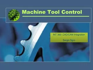
MACHINE TOOL VIBRATION AND DAMPERS
MACHINE TOOL VIBRATION AND DAMPERS. List of contents . Introduction Types of vibration Effects of vibration Sources of vibration excitation Vibration control in machine tool Damping Conclusion. Introduction.

MACHINE TOOL VIBRATION AND DAMPERS
E N D
Presentation Transcript
List of contents • Introduction • Types of vibration • Effects of vibration • Sources of vibration excitation • Vibration control in machine tool • Damping • Conclusion
Introduction • Machining and measuring operations are invariably accompanied by vibration. • To achieve higher accuracy and productivity vibration in machine tool must be controlled. • For analysis of dynamic behavior of machine tool rigidity and stability are two important characteristics.
Types of vibration • Machine tool vibrations may be divided into 3 basic types:- 1.Free or transient vibration 2.Forced vibration 3.Self excited vibration(Machine tool chatter)
Effects of vibration • The effect of vibration on machine tool:- Vibration may lead to complete or partial destruction of machine tool. Disturbing forces Origin Point of action Cutting process Work piece cutting tool Bearing, belts etc Bearings of shafts Motors Flanges, shafts Drives Guides, gear drives
Continue……… • The effect of vibration on the cutting condition Three effects on cutting condition 1.Chip thickness variation effect 2.Penetration rate variation effect 3.Cutting speed variation effect
Continue………. • The effect of vibration on the work piece • The major effect is poor surface finish. • It is very important for grinding machine. • Dimensional accuracy of job is also effected. • This is mostly due to chatter vibration. • Chatter marks are proof for the effect of vibration on the work piece
Continue…… • The effect of vibration on tool life Tool life = K / ( Vx. sm. tl) V-velocity S-uncut chip thickness t-width of cut Ceramic and diamond tools are sensitive to impact loading.
Sources of vibration excitation • Inhomogeneous work piece material • Hard spots or a crust in work piece leads to free vibrations. • Discontinuous chip removal results in fluctuation of the cutting thrust. • The breaking away of a built-up edge from the tool face also impart impulses to the cutting tool
Continue….. • Variation in chip cross section • variation in the cross-sectional area is due to the shape of the machined surface or due to the configuration of tool. • Pulses imparted to the tool and job. • Pulses have shallow fronts for turning of eccentric parts and steep fronts for slotted parts and for milling/broaching. • Bouncing of the cutting tool on machined surface can be minimized by closing the recess with a plug or with filler
Continue…….. Disturbances in the work piece and tool drives • Forced vibration induced by rotation of unbalanced member affect the surface finish & tool life. This can be eliminated by careful balancing or by self centering. • Rotating components should be placed in position where effect of unbalance is less.
Continue……. • Electric motors produce both rectilinear and torsional vibration. • Rectilinear vibrations are due to a non-uniform air gap between the stator & rotor, asymmetry of windings, unbalance, bearing irregularities, misalignment with driven shaft • Torsional vibration is due to various electrical irregularities.
Continue…… • Gear induced vibration are due to production irregularities, assembly errors, or distortion of mesh caused by deformation of shafts, bearings and housing under transmitted load. • All gear faults produce non-uniform rotation which effect the surface finish & tool life. • Belt drives are used as filters to suppress high frequency vibration, can induce their own forced vibration. • Any variation in effective belt radius change belt tension and belt velocity
Continue….. • This causes a variation of the bearing load and of the rotational velocity of the pulley. • Another source of belt-induced vibrations is variation of the elastic modulus along the belt length. • Flat belts generate less vibration than V belts because of their better homogeneity and because the disturbing force is less dependent on the belt tension.
Continue………… • A)Vibration is minimized when belt tension and normal grinding force point in the same direction. • (B) Large amplitudes may arise when the normal grinding force is substantially equal to the belt tension. • (C) Vibration due to centrifugal force is likely to be caused by an unbalance of the wheel.
Continue…… • Uniformity of feed motions is disturbed by, stick-slip. • The occurrence of stick-slip depends on the interaction of the following factors:- (1) The mass of the sliding body (2) The drive stiffness (3) The damping present in the drive (4) The sliding speed (5) The surface roughness of the sliding surfaces, and (6) The lubricant used. It is encountered only at low sliding speeds;
Continue……… • IMPACTS FROM MASSIVE PART REVERSALS • Reversal of reciprocating parts produce sharp impacts, which excite both low-frequency solid-body vibrations of the machine and high-frequency structural modes. • Occur in machine tool like surface grinder and in CNC, CMM. • Thedriving forces units have impulsive character and cause free decaying vibrations in bothsolid-body and structural modes.
Continue……… • These vibrations excite relative displacements in the work zone between the work-piece and the cutting or measuring tool. • Reduction in the adverse effects of the impulsive forces can be achieved by enhancing the structural stiffness and natural frequencies • Increase of structural damping as well as damping of mounting elements (vibration isolators) also results in a reduction in the decay time.
Continue…… • VIBRATION TRANSMITTED FROM THE ENVIRONMENT • Shock and vibration generated in presses, machine tools, internal-combustion engines, compressors etc., are transmitted through the foundation to other machines, which they may set into forced vibration. • Vibration transmitted through the floor may be reduced by vibration isolation.
Continue…. • MACHINE-TOOL CHATTER • Chatter is a self-excited vibration which is induced and maintained by forces generated by the cutting process. • It effects surface finish, tool life, production rate and also produce noise. • Chatter resistance of a machine tool is usually characterized by a maximum stable (i.e., not causing chatter vibration) depth of cut b lim.
Continue…… • Machine-tool chatter is essentially a problem of dynamic stability. A machine tool under vibration-free cutting conditions may be regarded as a dynamical system in steady-state motion. Systems of this kind may become dynamically unstable and break into oscillation around the steady motion
Vibration control in machine tool • The vibration behaviour of a machine tool can be improved by • A reduction of the Intensity of the sources of vibration • By enhancement of the effective static stiffness and damping. • By appropriate choice of cutting regimes, tool design, and work-piece design.
Continue…. • Abatement of the sources is important mainly for forced vibrations. • Stiffness and damping are important for both forced and self excited (chatter) vibrations. • Both parameters, especially stiffness, are critical for accuracy of machine tools, stiffness by reducing structural deformations from the cutting forces, and damping by accelerating the decay of transient vibrations.
Continue…. • application of vibration dampers and absorbers is an effective technique for the solution of machine-vibration problems. • Static stiffness ksis defined as the ratio of the static force Po, applied between tooland work-piece, to the resulting static deflection As between the points of force application.
Continue….. • A force applied in one coordinate direction is causing displacements in three coordinate directions; thus the stiffness of a machine tool can be characterized by a stiffness matrix. • only one or two stiffness are measured to characterize the machine tool. • frame parts are designed for high stiffness. • Damping is determined mainly by joints especially for steel welded frames .
Continue….. • Cast iron parts contribute more to the overall damping, while material damping in polymer-concrete and granite is much higher. • The stiffness of a structure is determined primarily by the stiffness of the most flexible component in the path of the force. • In many cases the most flexible components of the breakdown are local deformations in joints, i.e., bolted connections between relatively rigid elements such as column and bed, column and table, etc.
Continue…… (A) Old design, relatively flexible owing to deformation of flange. (B) New design, bolt placed in a pocket (A) or flange stiffened with ribs on both sides of bolt (B).
Continue………… • Welded structural components are usually stiffer than cast iron components but have a lower damping capacity. • A considerable increase in damping can be achieved by using interrupted welds, but at a price of reduced stiffness.
Continue……… • Tool Design • Sharp tools are more likely to chatter than slightly blunted tools. • Since narrow chips are less likely to lead to instability, a reduction of the approach angle of the cutting tool results in improved chatter behaviour. • With lathe tools, an increase in the rake angle may result in improvement • In tools having multiple cutting edges by making the distance between the adjacent cutting edges non-equal and/or making the helix angle of the cutting edges different for each cutting edge.
Continue….. • Variation of Cutting Conditions • small increase or decrease in speed may stabilize the cutting process. • In high-speed CNC machine tools, this can be achieved by continuous computer monitoring of vibratory conditions. • An increase in the feed rate is also beneficial in some types of machining (drilling, face milling, and the like).
Damping • The major part of the damping results from the interaction of joined components at slides or bolted joints. • The interaction of the structure with the foundation or highly damped vibration isolators also may produce a noticeable damping. • structural damping is significantly higher for frame components made of polymer-concrete compositions or granite.
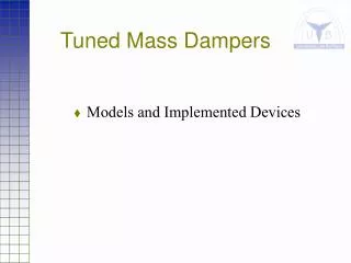
Continue…… • A significant damping increase can be achieved by filling internal cavities of the frame parts with a granular material. • For cast parts it can also be achieved by leaving cores in blind holes inside the casting. • Damping can be increased by the use of dampers and dynamic vibration absorbers. • Damping can be achieved by placing auxiliary longitudinal structural members inside longitudinal cavities within a frame part.
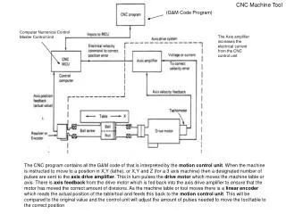
Continue…… • A variation of the Lanchester damper is frequently used in boring bars to good advantage.