CNC Machine Tool
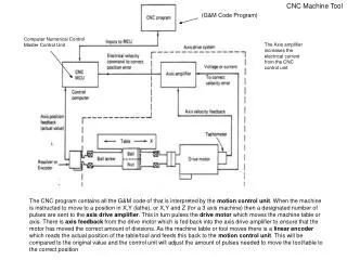
CNC Machine Tool. (G&M Code Program). Computer Numerical Control Master Control Unit. The Axis amplifier increases the electrical current from the CNC control unit.

CNC Machine Tool
E N D
Presentation Transcript
CNC Machine Tool (G&M Code Program) Computer Numerical Control Master Control Unit The Axis amplifier increases the electrical current from the CNC control unit The CNC program contains all the G&M code of that is interpreted by the motion control unit. When the machine is instructed to move to a position in X,Y (lathe), or X,Y and Z (for a 3 axis machine) then a designated number of pulses are sent to the axis drive amplifier. This in turn pulses the drive motor which moves the machine table or axis. There is axisfeedback from the drive motor which is fed back into the axis drive amplifier to ensure that the motor has moved the correct amount of divisions. As the machine table or tool moves there is a linear encoder which reads the actual position of the table/tool and feeds this back to the motion control unit. This will be compared to the original value and the control unit will adjust the amount of pulses needed to move the tool/table to the correct position
A Typical CNC Lathe/Milling Machine PLC = Programmable Logic Controller, This is a small computer with a built-in operating system (OS). This means that at the heart of the CNC machine is a computer. It may have a specialist operating system. NC = Numerical Control (This is the part program which is read / used by the CNC machine. It contains lines of instructions (G01;G00;T01; M04, etc) This is usually transferred to the machine via disk. Machine Control Unit = This part of the CNC machine is what interprets (breaks down) the part program and then instructs the various parts of the machine to switch on/off, move, etc Axis Servo Drive This will amplify the small electrical signals sent from the control unit into larger electrical signals which will then be transferred to the servo motor on the axis (X,Y,and Z) Servo Motor The servo motor will turn a number of degrees each time a pulse is sent to it from the axis servo drive. Each pulse may only move the machine 0.01mm. In order to move the machine 1mm the servo motor may have to be pulsed 100 times. Axis Positional Encoder This will send a positional value back to the machine control unit. Spindle Speed Encoder This will send a speed value back to the machine control unit. CNC Block Diagram
A Typical CNC Lathe/Milling Machine Program Being Interpreted by the Machine Control Unit CNC Program G and M codes Are axis at position? Send signals to servo interface for X and Z axis Servo interface to amplify signals Servo motors move axis Encoder sends Positional data To control unit G00 X20 z30 yes Is T01 Fitted? Electrical pulse to Tool change Is T01 Fitted? Request machine to have T01 fitted T01 yes yes no Is spindle at speed? Send signals to Spindle servo interface Servo interface to amplify signals Servo motors to rotate spindle Encoder sends Positional data To control unit M04 S200 yes no Are axis at position? Send signals to servo interface for X and Z axis Servo interface to amplify signals Servo motors move axis Encoder sends Positional data To control unit G01 X20 Z0 yes Program Continues
Machine Control Unit = This part of the CNC machine is what interprets (breaks down) the part program and then instructs the various parts of the machine to switch on/off, move, etc. It is a series of microcontrollers with an operating system. (typically a windows interface) Axis Servo Drive This will amplify the small electrical signals sent from the control unit into larger electrical signals which will then be transferred to the seperate servo motors on each of the axis slides (X,Y,and Z) Axis / Spindle Servo Motors The servo motors are mounted onto each slideway (X,Y,Z) and move the tool or the table of the machine. The servo motor will turn a number of degrees each time a pulse is sent to it from the axis servo drive. Each pulse may only move the machine 0.01mm. In order to move the machine 1mm the servo motor may have to be pulsed 100 times. Spindle servo motors may operate at much higher speeds than axis servo motors.
Axis Positional Encoder The CNC machine tools operate with a closed loop control system. For this purpose it is necessary to provide appropriate feedback in order to achieve accurate control of the movement of the axes. The feedback that are in general utilised are the displacement and velocities of the individual axes in the machine tool. The typical positional sensors used in the CNC machine tools are following: • Linear scales To know the exact position of the axis (slide position) it is important to have the absolute position read in a direct way (physically on the slide). The linear scale is a good method to do this. Linear means ‘in a straight line’. The linear scale consists of a finely graduated grating made of either glass or stainless steel that is the measuring surface attached to one part of the slide. A scanning unit is fixed to other part. The scanning unit consists of a light source (such as infra-red LED’s), which shine through a glass grid along graduated windows & some photo diodes as receptors to detect how many pulses of light are sent through the small holes in the ‘moire fringes’ The basic principle employed in such measurements is that when two gratings overlap each other, a Moirè fringe pattern is formed corresponding to the displacement. The actual distance moved can be calculated by measuring the shift in the fringe pattern CAD CAM – Principles and Applications - EBook http://books.google.co.uk/books?id=QaY_sQC4-5YC&pg=PT274&lpg=PT274&dq=cnc+moire+fringes&source=bl&ots=G7mQtEvmHe&sig=-9e4FOYHzpwc1zNBc3QjrOm2R3o&hl=en&sa=X&ei=r5ouUcHiA6qX1AWXtYGABw&ved=0CF8Q6AEwBw
2. Encoders The encoder is a transducer that is linked directly to the rotor or the lead screw and therefore does the simplest arrangement need no additional gearing. An optical rotary encoder changed the rotary motion of the motor into a sequence of digital pulses. The pulses counted to change to the position measurement. The optical encoder contains a disc having a number of accurately etched equidistant lines or slots along the periphery. The encoder disc is associated to the shaft of the machine whose rotary position has to be measured. The disc is placed between a light source (generally infra red LED) and a light measuring device (photo diode) as shown in Figure 6. When the disc rotates the lines are interrupted and the light measuring device counts the number of times the light is interrupted. By a careful counting and proper calculations it is possible to know the position traversed by the shaft. The rotary encoder is normally mounted on the servo motor shaft or at the end of the lead screw as illustrated. This allows the control to calculate the actual distance moved from the rotary motion by using the lead of the lead screw. If the lead screw contains any backlash, then that will be reflected in the position indicated by the encoder. Therefore it becomes mandatory to remove the backlash in the lead screw to correctly get the position of the axis. Also it requires that the pitch of the lead screw be more correct over its entire length for exact sensing of the position. http://www.expertsmind.com/topic/cnc-machine-tools/feedback-elements-99896.aspx
Advanced Positional Encoder (Increased Accuracy) This will send a positional value back to the machine control unit. How Do They Work?Uniquely coded inserts are placed between the precision balls in the scale. The inserts contain a small magnet that can be detected by a series of hall sensors contained in the reader head. The density of the inserts and the detectors within the reader head allows the encoder to determine fully absolute position. Once the encoder has determined the true absolute position it is then a matter for the Digital Signal Processor (DSP) to handle communication of the positional data to the control unit. Being a DSP based absolute system capable of a high level of processing; the encoders are error mapped during manufacturing against a laser interferometer. This error map is stored in FLASH memory allowing it to be applied in real-time thus resulting in a highly accurate encoder. http://www.newall.co.uk/products/?name=Absolute+Encoders+for+Feedback+for+CNC%2FPLC&catid=69
Spindle Speed Rotary Encoder This will send a series of pulses back to the machine control unit each time the spindle of the machine rotates once (as a measured number) to be converted by the control unit CPU and then compared to the requested speed (RPM or revolutions in m/min). If the spindle is running too fast or slow then the machine control unit will increase or decrease the amount of pulses it then sends to the spindle servo driver and then the spindle servo motors. It is called an incremental rotary encoder. The location of this encoder is to be mounted on the end of the spindle. When the spindle rotates the encoder shaft rotates at the same speed. An incremental encoder produces a known number ‘n’ of digital pulses for each 360-degree rotation of the encoder's shaft. (Each rotation of the shaft may produce 50 – 500 pulses) Manufacturers of Rotary Encoders and Positional Systems http://www.dynapar.com/Technology/Encoder_Basics/Incremental_Encoder/ http://www.pepperl-fuchs.co.uk/great_britain/en/classid_195.htm
Overview of CNC Machine The machine operator has to be safely protected from the hazards of the machine. If at any time the door is opened then a brpken signal is sent to the control unit which prevents the machine from being started, or it will stop if in-cycle and the door is opened. If during the program coolant is required then the operator can switch on the coolant pump manually using the keyboard or it may be started/stopped automatically in the program (M08=ON, M09=OFF) G&M Program Keyboard / Front Panel / Operators interface VDU Screen (Monitor) Machine Control Unit Safety switches (Door interlocks) Coolant Pump Magnetic (reed) switches Door interlocks Axis servo / motors Spindle servo / motors The VDU screen typically displays the program and any feedback from the machine control unit.