Geocomposite Subsurface Drainage Systems
Geocomposite Subsurface Drainage Systems. Presented by: Developed by: Aigen Zhao, PhD, PE Tenax Corporation VP/Engineering. CONTENTS OF PRESENTATION. Water in Pavement Systems Conventional Drainage Solutions Geocomposite Drainage Layer Solutions Drainage Requirements for Permeable Layer

Geocomposite Subsurface Drainage Systems
E N D
Presentation Transcript
Geocomposite Subsurface Drainage Systems Presented by: Developed by: Aigen Zhao, PhD, PE Tenax Corporation VP/Engineering
CONTENTS OF PRESENTATION • Water in Pavement Systems • Conventional Drainage Solutions • Geocomposite Drainage Layer Solutions • Drainage Requirements for Permeable Layer • Geocomposite Drainage Effectiveness • Cost Benefits • Case Histories
Related References • FHWA, 1992, Demonstration project 87: “Drainable pavement systems”, Participant Notebook, FHWA-SA-92-008. • US Army Corps of Engineers, 1992, “Engineering and design drainage layers for pavements”, Engineer Technical Letter, 1110-3-435, Department of Army. • Cedergren, 1987, “Drainage of highway and airfield pavements”, R. E. Krieger publishing Co, FL • Christopher and McGuffey, 1997, NCHRP Synthesis of highway practice 239, “Pavement subsurface drainage systems”, Transportation Research Board. • Christopher, Hayden, and Zhao, 1999, “Roadway Base and Subgrade Geocomposite Drainage Layers, “ ASTM STP 1390, American Society for Testing and Materials, June. • Christopher and Zhao, 2001, “Design manual for roadway geocomposite underdrain systems”, Tenax Corporation.
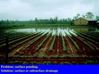
Standing water in a pavement indicates low permeability and poor drainage
Under traffic loading, water and base material squirting up through joint in PCC pavement
Water in Pavement Systems • AASHTO (1993) reports: • Water in the asphalt surface • Moisture damage, modulus reduction and loss of tensile strength • Saturation reduces dry modulus of the asphalt 30 % • Moisture in unbound aggregate base and subbase • Loss of stiffness 50 % • Water in asphalt-treated base • Modulus reduction of up to 30 percent • Increase erosion susceptibility of cement or lime treated bases • Saturated fine grained roadbed soil • Modulus reductions 50 % AASHTO Guide for Design of Pavement Structures, 1993
Severity factor measures the relative damage between wet and dry periods For a pavement section with a moderate severity factor of 10, if 10% of time the pavement is approaching saturation, the pavement service life could be reduced by half. Ref. Cedergren, H.R. 1987, Drainage of highway and airfield pavements, Robert E Krieger Publishing Co, FL.
AASHTO Drainage Definitions Quality of Drainage Excellent Good Fair Poor Very Poor Water Removed Within* 2 Hours 1 Day 1 Week 1 Month Water will not Drain *Based on time to drain AASHTO Guide for Design of Pavement Structures, 1993
Design for Drainage (AASHTO, 1993 Design Method) • Structural Number (SN) for a pavement section is: • SN = a1*d1 + a2*d2*m2 + a3*d3*m3 • a1 a2 a3 = layer coefficients for AC, BC and Sub base layers • d1, d2,d3 = their thickness • m2, m3 = drainage coefficients for the base and sub base layer
Recommended Drainage Coefficient, cd, for Rigid Pavements AASHTO Guide for Design of Pavement Structures, 1993
Recommended values for drainage modifier, mi, for untreated base and subbase materials in flexible pavements (AASHTO, 1993). Page. 6 Table 2 - from the Design Manual for Roadway Geocomposite Underdrain Systems By, Barry Christopher, Ph.D., P.E. and Aigen Zhao , Ph.D., P.E.
Components of a Drainable Pavement Christopher and McGuffey, 1997, NCHRP Synthesis 239, “Pavement subsurface drainage systems”
Time to Drain • For two lane road - Lane width = 24 ft, Slope = 0.01 Base k time to drain Quality OGB 1000 ft/day 2 hrs to drain Excellent DGAB 1 ft/day 1 week Fair DGAB w/ fines 0.1 ft/day 1 month Poor Reality no drains does not drain Very Poor
TRADEOFF OF STABILITY AND DRAINABILITY OF OGBC “Although the benefits of well-drained pavements have been clearly shown, there has always been hesitancy on the part of practitioners to use open-graded base courses because of concerns regarding a lack of stability of the open-graded layer…. There is doubt as to how long the hydraulic conductivity of open-graded bases can be maintained because of upward migration of subgrade soil particles into the layer, as well as, possibly, the infiltration of fine particles from fractures in the pavement surface….” TRB Committee A2K06 on Subsurface Drainage Research Proposal for NCHRP “STABILITY AND DRAINABILITY OF OPEN-GRADED BASE COURSES”
New Alternative Drainage Material:Geocomposite Drainage Layers Maine DOT
Tri-Planar RoaDrain Geocomposite to Replace Drainable Aggregate in Flexible Pavement Systems • Excellent Drainage • Enhanced design life • Energy absorbing to mitigate reflective cracks from the existing PCC base • Separation between new asphalt overlay and subbase Asphalt Pavement
Geocomposite to Replace Drainable Aggregate in Rigid or Flexible Pavement Systems • Drainage • For Rigid Pavements • Excellent drainage • Improved Design • > Cd
Enhance Drainage of Dense Graded Base by Shortening Drainage Distance • Drainage - • Improved Pavement Design • > m or Cd • > SN • Separation • Improved long term performance • Stabilization • Improved construction • Reinforcement • Improved Load Support
Sufficiently high inflow permeability to allow uninhibited flow from the adjacent pavement section during any major rainfall event Sufficient stiffness to support traffic without significant deformation under dynamic loading Sufficient transmissivity to rapidly drain the pavement section and prevent saturation of the base Sufficient air void exist within the geocomposite to provide a capillary break Geocomposite Drain Requirements Christopher, Hayden, and Zhao, “Roadway Base and Subgrade Geocomposite Drainage Layers, “ ASTM STP 1390, American Society for Testing and Materials, June,1999.
RoaDrainTM – Important Properties • High Transmissivity • Creep Resistance under High Loads • Long-term Resistance to Compression • Stability Traffic Loads = Univ. of Illinois Study • A Void-Maintaining Structure • Geotextile Filtration Requirements
Fatigue Test Setup and Representative Results(Univ. Of Il. Advanced Transportation Research and Engineering Lab)
Comparison of drainage performance with and without RoaDrain geocomposite drainage net. Page. 21 Table 3 - from the Design Manual for Roadway Geocomposite Underdrain Systems By, Barry Christopher, Ph.D., P.E. and Aigen Zhao , Ph.D., P.E.
Equivalency of RoaDrain to 4” OGBL – flow capacity • 4”- OGBL with (k =1000 – 3000 ft/day) transmissivity = 300-1000 ft3/day/ft • Flow rate @2% = 6 – 20 ft3/day/ft • RoaDrain Synthetic Drainable Base Layer (SDBL) transmissivity = 1500 ft3/day/ft @15kpsf and 2% after considering an equivalency factor between geocomposite drain and soil drain. • Flow rate @2% = 30 ft3/day/ft SDBL > OGBL
Frost Heave & RoaDrain as a Capillary Barrier Frost heave refers to the raising of a surface due to the formation of ice lenses in the underlying soil.
Solutions to Reduce Frost Damage • U.S. Army Corps of Engineers (1963): • Limit the amount of frost-susceptible soil subjected to freezing temperatures. • Design of adequate bearing capacity during the most critical climatic period • a significant increase in aggregate thickness
Solutions to Reduce Frost Damage – RoaDrain Capillary Break Pavement Non-frost susceptible base Frost penetration depth No this kind of ice lens Frost susceptible soil RoaDrain Capillary Barrier Water table • Capillary break must be placed between the ground water table and frost penetration depth • In addition to capillary rise, water flow to the freezing front is caused by an up-moving gradient related to temperature and pressure changes
US Army Cold Regions Research and Engineering Lab (CRREL) Study Concluded: • RoaDrain was a very effective capillary barrier and eliminated frost heave in specimens from the Maine DOT test site • Freezing did not cause any observable physical changes Henry and Affleck, “Freezing tests on lean clay with Tenax tri-planar geocomposite as capillary barrier”
Construction DetailsGeocomposite Placement • Plastic ties being secured • Seams sewn • 4 man-hours per 100’ of installation
Construction DetailsGeocomposite Placed Above Base Course cont. • Base course graded • Tack coat applied • Geocomposite placed • Pavement surface placed
RoaDrain – Good to Excellent Drainage Discharge during the first year of monitoring corresponds strongly with precipitation events and water table levels. Based on the AASHTO definitions for pavement drainage capacity , the quality of drainage in the RoaDrain test section is good to excellent.
Falling Weight Deflectometer (FWD) Results (Drainage Sections), Maine DOT The control section has a higher SN because it has 2-ft extra base fill due to poor subgrade conditions
VADOT-Route 58 Rehabilitation Project - Tack coat applied and geocomposite placement