NoC: MPSoC Communication Fabric
890 likes | 1.13k Vues
NoC: MPSoC Communication Fabric. Interconnection Networks (ELE 580) Shougata Ghosh 20 th Apr, 2006. Outline. MPSoC Network-On-Chip Synthesis of Irregular NoC OCP SystemC Cases: IBM CoreConnect Sonic Silicon Backplane CrossBow IPs. What are MPSoCs?.

NoC: MPSoC Communication Fabric
E N D
Presentation Transcript
NoC: MPSoC Communication Fabric Interconnection Networks (ELE 580) Shougata Ghosh 20th Apr, 2006
Outline • MPSoC • Network-On-Chip • Synthesis of Irregular NoC • OCP • SystemC • Cases: • IBM CoreConnect • Sonic Silicon Backplane • CrossBow IPs
What are MPSoCs? • MPSoC – Multiprocessor System-On-Chip • Most SoCs today use multiple processing cores • MPSoCs are characterised by heterogeneous multiprocessors • CPUs, IPs (Intellectual Properties), DSP cores, Memory, Communication Handler (USB, UART, etc)
Where are MPSoCs used? • Cell phones • Network Processors (Used by Telecomm. and networking to handle high data rates) • Digital Television and set-top boxes • High Definition Television • Video games (PS emotion engine)
Challenges • All MPSoC designs have the following requirements: • Speed • Power • Area • Application Performance • Time to market
Why Reinvent the wheel? • Why not use uniprocessor (3.4 GHz!!)? • PDAs are usually uniprocessor • Cannot keep up with real-time processing requirements • Slow for real-time data • Real-time processing requires “real” concurrency • Uniprocessors provide “apparent” concurrency through multitasking (OS) • Multiprocessors can provide concurrency required to handle real-time events
Need multiple Processors • Why not CMPs? • +CMPs are cheaper (reuse) • +Easier to program • -Unpredictable delays (ex: Snoopy cache) • -Need buffering to handle unpredictability
Area concerns • Configured CMPs would have unused resources • Special purpose PEs: • Don’t need to support unwanted processes • Faster • Area efficient • Power efficient • Can exploit known memory access patterns • Smaller Caches (Area savings)
Components • Hardware • Multiple processors • Non-programmable IPs • Memory • Communication Interface • Interface heterogeneous components to Comm. Network • Communication Network • Hierarchical (Busses) • NoC
Design Flow • System-level-synthesis • Top-down approach • Synthesis algo. ->SoC Arch. + SW Model from system-level specs. • Platform-based Design • Starts with Functional System Spec. + Predesigned Platform • Mapping & Scheduling of functions to HW/SW • Component-based Design • Bottom-up approach
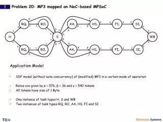
Platform Based Design • Start with functional Spec : Task Graphs • Task graph • Nodes: Tasks to complete • Edges: Communication and Dependence between tasks • Execution time on the nodes • Data communicated on the edges
Map tasks on pre designed HW • Use Extended Task Graph for SW and Communication
Mapping on to HW • Gantt chart: Scheduling task execution & Timing analysis • Extended Task Graph • Comm. Nodes • (Reads and Writes) • ILP and Heuristic Algo. to schedule Task and Comm. to HW and SW
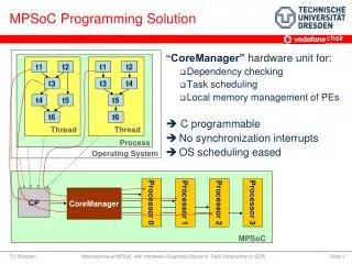
Component Based Design • Conceptual MPSoC Platform • SW, Processor, IP, Comm. Fabric • Parallel Development • Use APIs • Quicker time to market
Communication Fabric • Has been mostly Bus based • IBM CoreConnect, Sonic Silicon Backplane, etc. • Busses not scalable!! • Usually 5 Processors – rarely more than 10! • Number of cores has been increasing • Push towards NoC
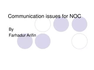
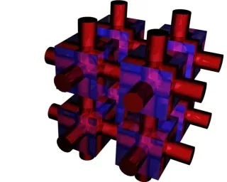
NoC NoC NoC-ing on Heaven’s Door!! • Typical Network-On-Chip (Regular)
Regular NoC • Bunch of tiles • Each tile has input (inject into network) and output (recv. From network) ports • Input port => 256-bit Data 38-bit Control • Network handles both static and dynamic traffic • Static: Flow of data from camera to MPEG encoder • Dynamic: Memory request from PE (or CPU) • Uses dedicated VC for static traffic • Dynamic traffic goes through arbitration
Control Bits • Control bit fields • Type (2 bits): Head, Body, Tail, Idle • Size (4 bits): Data size 0 (1-bit) to 8 (256-bit) • VC Mask (8 bits): Mask to determine VC (out of 8) Can be used to prioritise • Route (16 bits): Source routing • Ready (8 bits): Signal from network indicating it’s ready to accept the next flit (??why 8?)
Flow Control • Virtual Channel flow control • Router with input and output controller • Input controller has buffer and state for each VC • Inp. controller strips routing info from head flit • Flit arbitrates for output VC • Output VC has buffer for single flit • Used to store flit trying to get inp. buffer in next hop
NoC Issues • Basic difference between NoC and Inter-chip or Inter-board networks: • Wires and pins are ABUNDANT in NoC • Buffer space is limited in NoC • On-Chip pins for each tile could be 24,000 compared to 1000 for inter-chip designs • Designers can trade wiring resources for network performance! • Channels: • On-Chip => 300 bits • Inter-Chip => 8-16 bits
Topology • The previous design used folded torus • Folded torus has twice the wire demand and twice the bisection BW compared to mesh • Converts plentiful wires to bandwidth (performance) • Not hard to implement On-Chip • However, could be more power hungry
Flow Control Decision • Area scarce in On-Chip designs • Buffers use up a LOT of area • Flow control with less buffers are favourable • However, need to balance with performance • Dropping pkt. FC requires least buffer but at the expense of performance • Misrouting when enough path diversity
High Performance Circuits • Wiring regular and known at design time • Can be accurately modeled (R, L, C) • This enables: • Low swing circuit – 100mV compared to 1V • HUGE power saving • Overdrive produces 3 times signal velocity compared to full-swing drivers • Overdrive increases repeater spacing • Again significant power savings
Heterogeneous NoC • Regular topologies facilitate modular design and easily scaled up by replication • However, for heterogeneous systems, regular topologies lead to overdesigns!! • Heterogeneous NoCs can optimise local bottlenecks • Solution? • Complete Application Specific NoC synthesis flow • Customised topology and NoC building blocks
xPipe Lite • Application Specific NoC library • Creates application specific NoC • Uses library of NI, switch and link • Parameterised library modules optimised for frequency and low latency • Packet switched communication • Source routing • Wormhole flow control • Topology: Torus, Mesh, B-Tree, Butterfly
xPipes Lite • Uses OCP to communicate with cores • OCP advantages: • Industry wide standard for comm. protocol between cores and NoC • Allows parallel development of cores and NoC • Smoother development of modules • Faster time to market
xPipes Lite – Network Interface • Bridges OCP interface and NoC switching fabric • Functions: • Synch. Between OCP and xPipes timing • Packeting OCP transaction to flits • Route calculation • Flit buffering to improve performance
NI • Uses 2 registers to interface with OCP • Header reg. to store address (sent once) • Payload reg. to store data (sent multiple times for burst transfers) • Flits generated from the registers • Header flit from Header reg. • Body/payload flits from Payload reg. • Routing info. in header flit • Route determined from LUT using the dest. address
Network Interface • Bidirectional NI • Output stage identical to xPipes switches • Input stage uses dual-flit buffers • Uses the same flow control as the switches
Switch Architecture • xPipes switch is the basic building block of the switching fabric • 2-cycle latency • Output queued router • Fixed and round robin priority arbitration on input lines • Flow control • ACK/nACK • Go-Back-N semantics • CRC
Switch • Allocator module does the arbitration for head flit • Holds path until tail flit • Routing info requests the output port • The switch is parameterisable in: • Number of input/output, arbitration policy, output buffer sizes
Switch flow control • Input flit dropped if: • Requested output port held by previous packet • Output buffer full • Lost the arbitration • NACK sent back • All subsequent flits of that packet dropped until header flit reappears (Go-Back-N flow control) • Updates routing info for next switch
xPipes Lite - Links • The links are pipelined to overcome interconnect delay problem • xPipes Lite uses shallow pipelines for all modules (NI, Switch) • Low latency • Less buffer requirement • Area savings • Higher frequency
Heterogeneous Network • The network was heterogeneous in • Switch buffering • Input and Output ports • Arbitration policy • Links • Regular topology, however
Go-Back-N?? • Flow and Error Control • “Borrowed” from sliding window flow control • Reject all subsequent flits/packets after dropping • In sliding window flow control, NACKs are sent with frame number (N) • Sender has to go back to frame N and resend all the frames
NoC Synthesis - Netchip • Netchip – Tool to synthesise Application Specific NoCs • Uses two tools • SUNMAP – to generate/select topology • xPipes Lite – to generate NI, Switch, Links
Netchip • Three phases to generate the NoC • Topology Mapping – SUNMAP • Core Graph, Area/Power libs, Floorplan, Topology lib • Topology Selection – SUNMAP • NoC Generation – xPipes Lite • Possible to skip Phases 1 and 2 and provide custom topology!
Core Graph, Topology Graph • Core Graph: Directed Graph G(V, E) • Each vertex vi represents a SoC core • Each directed edge ei,j represents communication from vertex vi to vj • Weight of edge ei,j represents the bandwidth of communication from vi to vj • NoC Topology Graph: Directed Graph P(U, F) • Each vertex ui represents a node in the topology • Each directed edge fi,j represents communication from node ui to uj • Weight of edge fi,j (denoted by bwi,j) represents the bandwidth available across the edge fi,j
Mapping • Uses Minimum-path Mapping Algorithm to map the cores to the nodes • Do this for all topologies from the topology library
Selection • Torus, Mesh • 4 x 3 nodes • 5x5 switches • Butterfly • 4-ary 2-fly • 4x4 switches
What about irregular topologies? • Can be generated using Mixed Integer Linear Programming formulation “Linear Programming based Techniques for Synthesis of Network-on-Chip Architectures”, K. Srinivasan, K. Chatha and G. Konjevod, ASU
SystemC • System description language • Both C++ class library and Design Methodology • Provides hierarchical design that can address: • High-level abstraction • Low-level logic design • Simulate software algorithm