Download
1 / 23
230 likes | 457 Vues
Modifications to a TESLA cavity for CW high-current operations. Steve Lidia Center for Beam Physics E.O. Lawrence Berkeley National Laboratory. With contributions from C. Beard, M. Cordwell, D. Li, P. McIntosh, E. Wooldridge. Outline. Motivation Modifications to 7-cell TTF cavity

E N D
Modifications to a TESLA cavity for CW high-current operations Steve Lidia Center for Beam Physics E.O. Lawrence Berkeley National Laboratory With contributions from C. Beard, M. Cordwell, D. Li, P. McIntosh, E. Wooldridge Steve Lidia E.O. Lawrence Berkeley National Laboratory
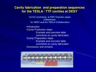
Outline • Motivation • Modifications to 7-cell TTF cavity • Optimization to end cell geometry • Pass-band behavior • External coupling benchmarking Steve Lidia E.O. Lawrence Berkeley National Laboratory
Motivation • High rep-rate (kHz - CW) SRF linacs are called for in many new accelerator designs (eg. ERLs, high average power FELs, etc.) • Many proven cavity/cryomodule designs work at low rep-rate (~10 Hz) and low average beam currents (~100 µA) • New cavity/cryomodules are designed to better handle: • High accelerating gradients (>~15 MV/m) • Higher average beam currents (>~100mA) • Larger HOM power dissipation • We are participating in a CCLRC/Cornell/Stanford/LBNL/FZR Rossendorf collaboration to build a next generation CW SCRF linac. Steve Lidia E.O. Lawrence Berkeley National Laboratory
ERLP Prototype Cryomodule Steve Lidia E.O. Lawrence Berkeley National Laboratory
Existing TTF 7-cell Design Optimized for low average current 103.3mm inner cell equatorial radius 104.8mm outer cell equatorial radius Steve Lidia E.O. Lawrence Berkeley National Laboratory
Modifications to TTF 7-Cell Cavity Central 5 cells + inner half cells remain identical to TTF 7-cell design End caps modified to balance field New high-power coaxial coupler and beampipe Steve Lidia E.O. Lawrence Berkeley National Laboratory
Cornell high-power coupler Input Couplers Steve Lidia E.O. Lawrence Berkeley National Laboratory
Cavity Geometry Optimization • The end cell cups and beam tubes are redesigned to provide sufficient field-flatness (< 0.5% rms), minimize surface fields, provide desired coupling in conjunction with the input coupler and propagation of HOMs to dampers. • Parametric models were created in Microwave Studio to allow easy variation of parameters and geometry generation. • Early studies indicated that the end cup slope provides very useful ‘knobs’ for optimization. Steve Lidia E.O. Lawrence Berkeley National Laboratory
1 104.8mm 35mm 39mm 123.1 mm C L End Cell Parameterization Input Coupler Elliptical Circular New Existing Steve Lidia E.O. Lawrence Berkeley National Laboratory
2 53mm 104.8mm C L End Cell Parameterization, cont’d. Existing New Steve Lidia E.O. Lawrence Berkeley National Laboratory
Peak-Cell-Amplitude RMS/Average % 29.125° ~0.3% End cell slope, 2 [°] Optimization of End Cell Slope Steve Lidia E.O. Lawrence Berkeley National Laboratory
-Mode Axial E-field Profile /Avg = 0.3% Average Steve Lidia E.O. Lawrence Berkeley National Laboratory
-Mode Fields E-field f = 1300.75 GHz Qext = 1 107 Surface fields Emax/Eacc = 2.9 Hmax/Eacc = 59.5 Oe/MV/m H-field Steve Lidia E.O. Lawrence Berkeley National Laboratory
-mode fNearest neighbor ~1.2 MHz fPi-Zero ~23 MHz 0-mode Coupled Modes in TM010 Pass-band Steve Lidia E.O. Lawrence Berkeley National Laboratory
External Coupling to TM010 Pass Band Zero mode Pi mode Steve Lidia E.O. Lawrence Berkeley National Laboratory
Optimum position Variation of Qext with Coupler Position Steve Lidia E.O. Lawrence Berkeley National Laboratory
Calculation of Qext • ‘Standard’ methods (eg. Kroll-Yu, Balleyguier, etc.) work well with low Qext structures, but lose accuracy with high Qext. • Microwave Studio has facilities for calculating Qext within a frequency domain simulation environment. Is it correct? • Time domain methods that observe field decay require excessively long simulation times for high-Q structures. • Time domain methods observing the field buildup can provide high accuracy with relatively short simulation times. • Multiple modes can complicate matters . . . • Simple models are useful to benchmark techniques. Steve Lidia E.O. Lawrence Berkeley National Laboratory
Coupler Benchmarking - Eigenmode TM010 mode 1.3 GHz Coaxial coupler Axial modal electric field Frequency domain parameters relate on-axis peak field, voltage, stored energy, etc. for mode. Steve Lidia E.O. Lawrence Berkeley National Laboratory
Coupler Benchmarking - Excitation/Response Field probes: Electric Magnetic Forward wave voltage Cavity probe response cosrest t cos(rest+0) Steve Lidia E.O. Lawrence Berkeley National Laboratory
Circuit equation for mode voltage evolution Factor out fast oscillation, and drive on-resonance Integrate from t=0 to t=T, (constant amplitude drive) Short duration, 0T << 2QL Relate to measured quantities Coupler Benchmarking - Analytical Remarks Steve Lidia E.O. Lawrence Berkeley National Laboratory
Eigenmode parameters Comparing Frequency and Time Domain Simulations Time domain results Excellent agreement for single modes! Microwave Studio simulations Steve Lidia E.O. Lawrence Berkeley National Laboratory
Summary • Work to redesign proven L-band SRF cavity technology for ERL application is underway. • Simple changes to the cavity end cell geometry permit the addition of high power input couplers while guaranteeing field flatness specifications. • We have found time domain methods to easily calculate external Q-factors for high-Q cavities, without unreasonably expensive computational runs. • Near term work will focus on HOM modeling and loss- and kick- factor calculation. Steve Lidia E.O. Lawrence Berkeley National Laboratory
- fin - Steve Lidia E.O. Lawrence Berkeley National Laboratory