Download
1 / 23
230 likes | 446 Vues
Cavity fabrication and preparation sequences for the TESLA / TTF cavities at DESY 1st ILC workshop at KEK Tsukuba Japan A.Matheisen for DESY and the TESLA Collaboration. Introduction Cavity Production steps Example and overview table comments on cavity fabrication

E N D
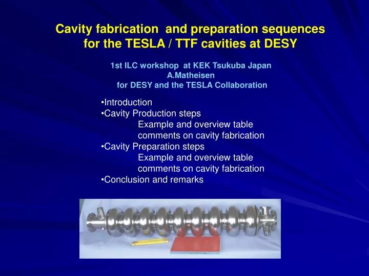
Cavity fabrication and preparation sequences for the TESLA / TTF cavities at DESY 1st ILC workshop at KEK Tsukuba Japan A.Matheisen for DESY and the TESLA Collaboration • Introduction • Cavity Production steps • Example and overview table • comments on cavity fabrication • Cavity Preparation steps • Example and overview table • comments on cavity fabrication • Conclusion and remarks
Introduction Since 1990 DESY and the TESLA collaboration have put a lot of activities in the field of srf cavities to study and prepare the build up of a TEV superconducting linear accelerator / TESLA The choice was made on 1.3 Ghz 9 cell geometry State of the art of acceleration field gradient was 5 MV/m for multi-cell cavity in “medium” scale production Lots of promising attempts and receipts on single cell were around ( HPP-Cornell / closed BCP /-SACLAY/ HPR - CERN Within the TESLA collaboration a test and preparation facility was set up at DESY • Decision was made to • Order Cavities in Industry, qualify companies, • learn on large scale production • Preparation und testing at DESY • ( multiple choice of preparation/ no clear receipt / • no specified facility available)
Cavity fabrication • Cavity fabrication was set up in close connection • with industrial companies • Each company had its characteristic in manufacturing • and specially in welding technique General fabrication steps applied in all companies are presented here
Hantel Dumb-bell Stützring Normalhalb- Zelle Normalhalb- Zelle Nb-Blech Normalhalelle Nb-Blech Normalhalbzelle Overview over cavity fabrication Cavity (9 cell TESLA /TTF design) Cavity (9 Zeller) Endhalbzell- Endrohr- Einheit lang End group 2 Endhalbzell- Endrohr- Einheit kurz End group 1 Endhalbzelle kurz Flansch (Hauptkoppler- Stutzen) Hauptkoppler- stutzen Flansch (Endflansch) Flansch (end-kurz-lang) Bordscheibe lange Seite Endhalbzelle lang Antennenstutzen lang Anbindung (end-kurz-lang) Endrohr kurz HOM-Koppler kurze Seite Rippe Rippe Flansch (Endflansch) HOM-Koppler lange Seite Endrohr lang HOM-Koppler DESY End-kurz-lang Formteil F Antennenflansch NW 12 Antennenflansch NW 12 HOM-Koppler DESY End-kurz-lang Formteil F lang
Hantel dumb bell Stützring Normalhalb- Zelle Normalhalb- Zelle Nb-Blech Normalhalelle Nb-Blech Normalhalbzelle Overview over cavity fabrication Cavity (9 Zeller) Cavity (9 Zeller)
Cavity fabrication : Example dumb bell / Cavity • Mechanical measurement • Cleaning (by ultra sonic [us] cleaning +rinsing) • Trimming of iris region and reshaping of cups if needed • Cleaning • Rf measurement of cups • Buffered chemical polishing + Rinsing (for welding of Iris) 7. Welding of Iris 8. Welding of stiffening rings 9. Mechanical measurement of dumb-bells 10. Reshaping of dumb bell if needed 11. Cleaning 12. Rf measurement of dumb-bell 13. Trimming of dumb-bells ( Equator regions ) 14. Cleaning 15. Intermediate chemical etching ( BCP /20- 40 µm )+ Rinsing 16. Visual Inspection of the inner surface of the dumb-bell local grinding if needed + (second chemical treatment + inspection ) Dumb- bell Dumb-bell ready for cavity
3 1 piece 1 pieces 7 pieces 1 2 Cavity welding: the general way There are differences of welding processes in industry • Degreasing and rinsing of parts • Drying under clean condition • Chemical etching at the welding area ( Equator) • Careful and intensive rinsing with ultra pure water • Dry under clean conditions • Install parts to fixture under clean conditions • Install parts into electron beam (eb) welding chamber • ( no contamination on the weld area allowed) • Install vacuum in the eb welding chamber <= 1E-5 mbar • Welding and cool down of Nb to T< 60 C before venting • Leak check of weld
Experiences on cavity fabrication: Deep drawing: 1. Reproducibility depends on tool design and tool material specification – investigation in tooling 2. Dependency on Nb supplier found 3. Different shape from ingot to ingot found (Hardness / grain size) Better quality control + specification reproducibility • Measurements: • 1. Rf measurement of cups / dumb bells Time consuming • Mechanical measurements of sub units Time consuming • ( F part HOM tube / flanges /dumb-bell3 D measurement complex combination of mechanical and rf measurement possible ? ( 3 D imaging of units) Fabrication: • Sequences need to be adopted to the company hardware • Companies need to be trained an stay trained • learning curve to stable production • Control on subcontractors • Dependency on major products of company training of personal
Cavity preparation General comment Actually more than 50 steps are in the line O Some steps of the preparation are related to the specific hardware With a modified hardware they might be eliminated Example: Entering procedure for cleanroom Procedure Car wash + Ultrasonic cleaning + ultra pure water rinsing+ drying inside cleanroom They will be display as O Some steps are common for all processes independent on BCP or EP processing They will be outlined by = italic letters
EP / 1 EP / 2 BCP Standard treatment used for TTF Modules 1-5 (BCP treatments + 1400 C titanium post purification) Standard treatment used for TTF Modules 1-5 (BCP treatments + 1400 C titanium post purification) Treatment sequence used for the first batch of cavities electro-polished in collaboration with KEK Combination of BCP (80- 160 µm)+ EP (80- 100µm) at KEK+ EP (20-50 µm) at DESY Part of production 1400 C titanium post purified Treatment sequence under study at DESY No 1400 C Ti post purification Only EP applied (200µm) Improved handling sequences Cavity Preparation Actually there are 3 general lines
The preparation process can be split up into 4 major steps Preparation step A Removal of demage layer / post purification / tuning Preparation step B Final cleaning and assembly for vertical test Preparation step C Welding of connection to He vessel / He vessel welding Preparation step D Final cleaning and assembly for module / horizontal test
Part A of preparation • Rf measurements and mechanical inspection • Chemical etching of cavity inside (CP 80 µm + clean water rinsing) • Chemical etching of cavity outside (>20 µm+ clean water rinsing) • Annealing and H2 outgasing in UHV oven at 800 C • 5. Rinsing in ultra pure water • 6. Insertion to 1400 C UHV oven ( inside DESY cleanroom ) • 7. Chemical etching (Removal of Titanium surface layer) • cavity inside (CP 80 µm + clean water rinsing) • outside ( 40 µm+ clean water rinsing) Cavity preparation (BCP) As example the BCP treatment use for sequence Module 1-5 at TTF Treatment includes post-purification by Titanium at 1400 C
Cavity preparation (BCP) • Part Bof preparation • Tuning of field profile • Chemical etching of cavity inside • (“final” BCP [ 20 µm ] + clean water rinsing) • 3. High pressure rinsing • 4. Drying in class 10 clean room air 12 h • 5. Assembly of auxiliaries • 6. Vacuum leak check of flange connections • 7. Venting and dismount pumping flange ( beampipe ) • 8. 1st high pressure • 9. 2nd high pressure rinse • 10. Drying over night in class 10 cleanroom • 11. Install antenna for vertical rf measurements Rf Measurement at 2 K
Cavity preparation (BCP) Rf Measurement at 2 K Part C of preparation Here major differences for BCP and EP cavities appear !!! • Enter cleanroom after rf test • 2. Venting of cavity • 3. Removal of variable Antenna • 4.Installation of pumping valve • 5. Install Argon atmosphere inside cavity • 6. Transport for welding of interconnection ring NB to Titanium • 7. Venting of cavity • 8. Removal of flanges (beampipe / Input coupler port) • 9. Measure and install fieldprofile • 10.Weld helium vessel • 11. Leak check of vessel welds
Cavity preparation (BCP) • Part D of preparation • Entering the clean room after tank welding • Chemical etching of cavity inside (BCP 20 µm + clean water rinsing) • High pressure rinsing • Drying in class 10 clean room air 12 h • Assembly of HOM Coupler / Pick Up probe / Flanges • Vacuum leak check of flange connections • Venting and dismount pumping flange ( beampipe ) • 1st high pressure • 2nd high pressure rinse • Drying over night in class 10 cleanroom • Mount pumping port for leack check and mass spectrometry • Leak check • Mount horizontal platform • Vent cavity for coupler installation • dismount coupler port blind flange • Install power coupler • Final leak check
Cavity preparation for electro polished cavities Part C of Cavity preparation has major differences for electro polished cavities qualified to 35 MV/m This part of the preparation was set up on the basis that a final surface treatment can be don when the helium vessel is installed But up to now no qualified and reproducible procedure for This preparation step on Electro-polishing of cavities with tanks is available
Cavity preparation for electro polishing EP 1 Part C of Cavity preparation Reentering cleanroom after rf test Remove variable Antenna Install bead pull and measure field profile inside cleanroom Adjust fieldprofile (outside of cleanroom Installation of antennas for mode spectrum control High pressure rinsing Install Argon atmosphere inside cavity Transport for welding of interconnection ring NB to Titanium Venting of cavity Removal of antennas Install bead pull and measure field profile inside cleanroom High pressure rinsing Adjust fieldprofile outside of cleanroom Remove bead pull system High pressure rinsing install of antennas for mode spectrum analysis Weld helium vessel Leak check of vessel welds 2 cavities lost gradient due to not well established manipulation
This procedures are much too complicated Way out is to install bead pull and rf antennas that go with the cavity on that process ? cavity interior sealed inside the cleanroom hermetically until preparation for Module / horizontal test ( under investigation) Way out development of final treatment on dressed cavities ? Light BCP ? Oxi polishing ? Cavity ep with tank ?
conclusion Cavity production in industry has to set up with good results We learned . That the Production is depending on company specific ways Industry need training and sensitization for the cavity production The rise up time until stable production is company depending
conclusion • Procedures for cavity treatment are available • We learned that • - Only when the procedures are followed strictly the results are stable • - Any missing step leads to cavity performance degradation • - Errors in the sequence need a step back in the process • - Any changes in the process, even small once have impact on others steps • and needs a reestablishing and a new qualification of the procedure • - Cavity results on single cell are not one to one transferable to multi-cells • Changes in a procedure has to be qualified on 9 cell cavities • - For Electro polished cavities investigations on the reproducibility of the process are needed • - Investigations on final treatment after vertical measurements have • to be made to have a smooth and reliable process after vertical measurements