MICE RF Cavity Measurements
130 likes | 324 Vues
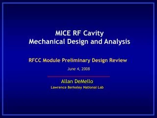
MICE RF Cavity Measurements. Derun Li Center for Beam Physics Lawrence Berkeley National Laboratory July 8, 2010 Rutherford Appleton Laboratory, UK. Summary. Cavity fabrication status The first five MICE RF cavity bodies are at LBNL (received in December of 2009)

MICE RF Cavity Measurements
E N D
Presentation Transcript
MICE RF Cavity Measurements Derun Li Center for Beam Physics Lawrence Berkeley National Laboratory July 8, 2010 Rutherford Appleton Laboratory, UK
Summary • Cavity fabrication status • The first five MICE RF cavity bodies are at LBNL (received in December of 2009) • The second five MICE RF cavities expect to arrive at LBNL in September of 2010 • Cavity measurements • Completion of CMM and low power RF measurements of the first five MICE cavities • Auxiliary components of the cavity • Three completed Be windows at LBNL now, 11 windows have been ordered and expect to receive the remainingeight in next two months. • RF coupler fabrication in progress & purchase order of 10 ceramic RF windows in process • Progress on RFCC module, RF tuner design, prototype and tests (Virsotek’s talk) • Near term plans MICE RF Cavity Measurement, D. Li, Lawrence Berkeley National Lab, July 8, 2010
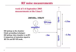
Preparation for RF measurements Lifting fixtures Be window Open iris Cavity stand for RF measurements and assembly, March 2010 MICE RF Cavity Measurement, D. Li, Lawrence Berkeley National Lab, July 8, 2010
RF measurements Two curved Be windows (#1 and #2) used as references for all the cavity measurements; require minimum three measurements to determine cavity body frequency Be window installation Installation of Be windows for RF measurements, March 2010 MICE RF Cavity Measurement, D. Li, Lawrence Berkeley National Lab, July 8, 2010
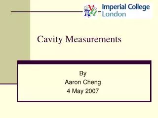
RF Measurement Setup, Results RF probes, excitation & pickup NWA S11 measurements S21 measurements MICE RF Cavity Measurement, D. Li, Lawrence Berkeley National Lab, July 8, 2010
MICE Cavity Design Parameters • The cavity design parameters • Frequency: 201.25 MHz • β = 0.87 • Shunt impedance (VT2/P): ~ 22 MΩ/m • Quality factor (Q0): ~ 53,500 • Be window diameter and thickness: 42-cm and 0.38-mm • Nominal parameters for MICE and cooling channels in a neutrino factory • 8 MV/m (~16 MV/m) peak accelerating field • Peak input RF power: 1 MW (~4.6 MW) per cavity • Average power dissipation per cavity: 1 kW (~8.4 kW) • Average power dissipation per Be window: 12 watts (~100 watts) MICE RF Cavity Measurement, D. Li, Lawrence Berkeley National Lab, July 8, 2010
Measurement Results • The first five MICE cavities have been measured in three different window configurations using Be windows #1 and #2 (reference windows) *no water cooling tube brazed to the cavity body • Average center frequency of the cavity body (#1 to #4) = 200.990 MHz; frequency variations among the cavities ± 254 kHz (within our expectations) • Q measurements of the first five MICE cavities: 42,000 – 44, 600 (~ 80% of the design Q) (S21 measurements using 2 probes with all ports terminated) MICE RF Cavity Measurement, D. Li, Lawrence Berkeley National Lab, July 8, 2010
Measurement Data Analysis - Δf1 Window # 1 Cavity body frequency:fbody Window # 2 + Δf2 MICE RF Cavity Measurement, D. Li, Lawrence Berkeley National Lab, July 8, 2010
Analysis of the Measurements • Additional RF measurements to study frequency shifts due to each RF port • Frequency shift of one RF port (from open to short) : +11 kHz/port (S11 measurements) • Preliminary analysis • Definition of a cavity body frequency (approximately equivalent to the iris terminated by flat metal sheet/window, fbody • Assuming the curved Be windows introduce frequency shifts of +Δf1 (out) by window #1 and - Δf2 (in) by window #2 and neglecting higher order frequency shifts due to local field changes by the curved window, therefore: Measured frequency ≈ fbody ± Δf1 ± Δf2 • The “±” depends on Be window configurations (curved-in or -out of the cavity body) • Require three measurements to determine fbody , Δf1andΔf2 MICE RF Cavity Measurement, D. Li, Lawrence Berkeley National Lab, July 8, 2010
Data Analysis (cont’d) • Curved Be windows • Measured three windows so far • Frequency shifts from curved-in and curved-out are different • For a given window configuration, the cavity frequency can be predicted within less than 20 kHz using the formulae and measured frequencies of the cavity body and the windows • Conclusions: • Profiles of the two windows must be different ( 100 kHz or less) • Cavity frequency variation within ± 254 kHz • Be windows can be used as additional tuning knobs, find best pairs to match with cavities MICE RF Cavity Measurement, D. Li, Lawrence Berkeley National Lab, July 8, 2010
Near Term Plans • Low power RF measurements • The 2nd batch of five MICE cavities • Find center (average) frequency of all (8) MICE cavities • Tune cavity a center frequency, in combination with best pair of Be windows predicted by the formula • Cavity fabrication and assembly • Modified port extruding technique at Applied Fusion • Better control of local temperature using torch • Ports: more consistent, less sagging and good finish • Oxidation: argon purge during extruding process • Be windows, tuners, RF couplers, RF windows and vacuum vessels • Post-processing • Electro-polishing and cleaning • Identified a local company (San Francisco Bay Areas) MICE RF Cavity Measurement, D. Li, Lawrence Berkeley National Lab, July 8, 2010
Near Term Plans (cont’d) • Production of the second batch of five MICE cavities at Applied Fusion • Nose rings • Port extruding and flanges • Braze water cooling tubes • Modified extruding technique • Experimented using the test cavity • Need argon gas purge to prevent oxidation of cavity surface • Measure oxidation layer thickness MICE RF Cavity Measurement, D. Li, Lawrence Berkeley National Lab, July 8, 2010
Near Term Plans (cont’d) • EP: vendor visit 398 Railroad Ct., Milpitas CA 95035 • The inside surface of each cavity needs to be electro-polished • Electro-polish tank dimensions: 12' Long x 5' Wide x 6' Deep • EP test using the test cavity MICE RF Cavity Measurement, D. Li, Lawrence Berkeley National Lab, July 8, 2010