RF Cavity Module
RF Cavity Module. G. Gosling Dept. of Mechanical Engineering Imperial College London. What is it?. Schematic of proposed arrangement of Muon Ionisation Cooling Experiment. When is it needed for?. April 2007 2009. What is in it?. Coupling Magnets. 2 required, one per set of cavities.


RF Cavity Module
E N D
Presentation Transcript
RF Cavity Module G. Gosling Dept. of Mechanical Engineering Imperial College London
What is it? Schematic of proposed arrangement of Muon Ionisation Cooling Experiment.
When is it needed for? April 2007 2009
Coupling Magnets • 2 required, one per set of cavities. • Size and specification known. • Similar to Medical Imaging magnets. • Complete with independant cooling. • Major money £500k each.
Vacuum Pumps • Precise requirement, no clear at present. • MICE needs: • High level of vacuum • Vacuum in side Shell (inside & outside Cavities) • Superior quality inside cavity • Possibly one pump per cavity.
RF Supply • 2 Couplers per cavity. • Design problem of how to access RF supply through Shell and Cavity. • Flexible connection • Expensive ceramic insulators (£15k each)
What is the current progress? • Lawrence Berkeley National Labs have designed & built a prototype cavity. • Start some testing in April 2005 at Fermilab in US. • Much still has to be done: • In service testing • Remaining first-time design
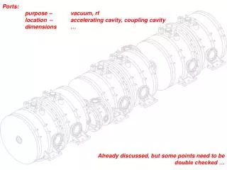
RF Cavity Overview • Two 6 mm thick copper shells are welded together to form cavity. • RF and vacuum ports are formed by extruding across equator weld. • Two thin, pre-curved beryllium windows are mounted on cavity. • Cold water system for temperature control of the cavity. • Cavity inside surfaces are finished by electro-polishing.
Cavity Shell Spinning • Start with a 1.4m square of 6.35mm OFHC copper sheet. • Spin against a pre-machined form to generate half-shell with the appropriate shape. • Not a precision process, involves the cold working of a ductile material. • Similar to potters wheel. • Used for making lorry wheels and large dishes.
Equator Joint Machining • Shell lips are cut using CNC machining. • Lip detail includes a chamfered step that mates with the opposing shell • The step locks the shell edges together and prevents slipping prior to and during e-beam welding
Electron Beam Weld • Cavity and fixture system is mounted and assembled on a plate and placed on the welder table • External structural weld is near full penetration and is achieved in three offset passes • A final cosmetic/vacuum weld is performed on the inside of the joint with the cavity mounted on a horizontal rotary table
Nose Fabrication • A stainless steel support ring is brazed to a copper backing ring. • SS ring has a bolt circle for attaching Be window. • Copper backing ring is then Electron Beam welded to cavity.
Cavity Port Forming • Port pulling tool is used in a horizontal orientation. • A weld prep is machined into the port lip using a numerically controlled mill.
Port Flange E-beam Weld • Cavity is held vertically in welder chamber on a fixture that facilitates 90 degree rotations • Structural and vacuum weld is achieved using a single inside pass • Prototype cavity uses a stainless flange with a TIG welded copper insert (flange must hold vacuum)
Cooling Tube Weld • Cavity cooling to be achieved by TIG brazing a 9.5 mm diameter copper tube to the outer surfaces • Nominal flow rate is 3 gpm per circuit
What is the next step? • Electro-polishing of internal surfaces. • Obtain and fit Beryllium window. • Fermilab tests.
Shell Cleaning and Buffing • Scratches and dents are created on the surfaces during spinning. • Cavity surfaces and welds are smoothed out mechanically as they occur. • Final cavity requires electro-polishing to achieve required internal surface quality.
Beryllium Windows • Each cavity will require a pair of 0.38 mm thick pre-curved beryllium windows • Copper frame is brazed to beryllium window in a subsequent process • Curved shape prevents buckling caused by RF heating • Third time lucky for producer, • One warped • One cracked
Fermilab test conditions • Cavity will be rigidly bolted through both stiffener rings to free-standing fixture. • Cavity will work in atmospheric conditions under internal vacuum. • Tuning will be conducted manually and must compensate for operating pressure difference.
Cavity Tuning System • Tuners push or pull on stiffener rings to deform cavity and adjust frequency, • ± 2 mm of motion required (expected), • Must be remotely controlled. • Current concept incorporates a scissor jack type linkage to gain both mechanical advantage and resolution • Actuation forces likely to be hydraulic due to high magnetic fields
What is still left to do? • UK opportunity for involvement in detailed design & development of: • Hydraulic Tuning device, • Support for Cavity inside Main shells. • No current design work ongoing at LBNL.
How much will it cost • Key hardware costs: • £1 Million on Coupling Magnet assys • £250k of RF couplers • £250k on Cavity hardware • Design/Development costs • Unknown extent • Need for prototyping to assess remaining design and development work
Unknowns? • Cavity and Shell parameters for: • Lack of space around cavities, limited by coupling magnet. • Manufacturing tolerances, imprecise processes. • Behaviour under running conditions. • Operators’ requirements, temperature ranges and response requirements.
Yes, with exceptions Cavities Shell Magnets Liquid H Absorber Beryllium Windows Vacuum Pumps Yes Yes Yes ? (Oxford study) No Yes Could we build them in the UK?