Commissioning of Crab Cavities for High-Current Beams in KEKB: Overview and Findings
320 likes | 442 Vues
This document presents a comprehensive introduction to the commissioning and operational aspects of crab cavities at the KEKB accelerator complex, focusing on their role in enhancing luminosity through crab crossing schemes for high-current e+/e- beams. It discusses the frequency tuning mechanisms, beam-induced RF spectra, and operational challenges experienced during initial physics runs. Key findings include oscillation patterns at high currents and techniques to mitigate trip rates and improve stability. The results from various operational periods and detailed tuning strategies provide valuable insights into effective crab cavity management.

Commissioning of Crab Cavities for High-Current Beams in KEKB: Overview and Findings
E N D
Presentation Transcript
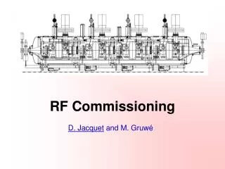
KEKB RF Cavity Commissioning and Operation Introduction Commissioning Frequency tuner Oscillation of high current crabbing beam Trip rate HOM dampers Beam-induced RF spectrum Summary Yoshiyuki MORITA KEK
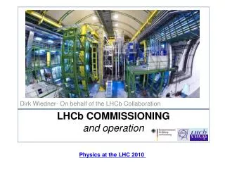
KEKB He Refrigerator LER Crab cavity LER: e+ 3.5 GeV 1.7A HER: e- 8.0 GeV 1.4A RF freq.: 509 MHz Cross. Angle: 22 mrad BELLE IP 8 SC cavities HER HER Crab cavity LER ARES cavities ARES cavities Present crab crossing scheme e+ Linac • One cavity in one ring • Beam bunches wiggle in the ring • Luminosity increase (K. Ohmi) • NIKKO AREA • ~1 km away from the IP • He refrigerator (8 kW@4.4K) • Reduce the construction costs e- Linac
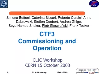
K. Akai Unique characteristics • Coaxial Coupler • Squashed Cell • High Field Vkick=1.4 MV Esp=21 MV/m Crab CavityConceptual Design (RF Absorber) Crab Mode: TM110-like mode (high R/Q) Coaxial coupler: LOM damping Squashed cell: UWP > 600 MHz Notch filter: TEM-coupled Crab mode rejection Stub support: support for inner conductor
Commissioning and operation • Coupler aging at room temperature (up to 200 kW) • Cool down (2 K/h for 1 week) • Tuner adjustment • Cavity conditioning • HER: >1.8 MV • LER: 1.5 -> 1.3 -> 1.1 MV • Low beam current tuning for crab crossing • Warm-up to 80 K and to room temperature • High current operation and physics run
System adjustment • Crabbing voltage • R/Q, Input RF power, Qext measured at Horizontal test • Field center • Beam-induced crabbing amplitude with crab detuned • Local bump orbit • Crabbing phase • Beam orbit difference (Crab ON/OFF) • Determine crabbing phase • Determine crabbing voltage • Tilting angle of beam bunch • Streak camera (H. Ikeda) HER LER
Overview of the crab commissioning (1st period) HER 0.7A (crab ON) 1.35A(detuned) 1.2A(detuned) LER 3/17 Vc degraded to 1 MV High trip rate 1.3A (crab ON) 1.7A(detuned) 1.4A(detuned) 2/19 First crabbed beam 2/21 First crab collision Warm-up to 80 K Warm-up to 80 K Warm-up to 300 K 2nd high current trial 1st high current trial Conditioning Crab detuned Crab detuned
Overview of the crab commissioning (2nd and 3rd periods) Physics run with crab ON HER 0.95A (crab ON) LER 1.62A (crab ON) Winter shutdown 3.5 spacing 3.06 spacing (Oct. 26)
K. Hosoyama Frequency Tuner Support Pipe Tuning Rod Driving Plate Input Coupler Sub Tuner Mechanical Main Liq. He Vessel Pick up Probe Bellows Beam Main Tuner Mechanical + Piezo Stub Support RF Monitor Coaxial Coupler Sub Liq. He Vessel Main tuner (motor+piezo): Frequency tuning (21 kHz/mm) Sub tuner (motor): Alignment of the coaxial coupler Pick-up probe for monitoring crabbing-mode leakage Frequency Tuning ~30 kHz / mm Adjust the Tip Position of Coaxial Coupler Cryostat Vacuum End Cell
Tuner test A. Kabe Tuning parameter: 21 kHz/mm Fluctuation: +/-1 deg. Alignment of the coax Main tuner (piezo) Main tuner (motor) Sub tuner (motor) Fluctuation: +/-13 deg.
Tuning mechanism improvement A. Kabe • Piezo actuators broke several times. • HER: 2 (Oct., 2007) • LER: 2 (June, 2007), 1(Oct, 2007) • Coil spring added. (Jan., 2008) • No breakdown since then • Pulling force is the cause ? Load cell Shaft guide Shaft Coil spring
LER crab phase ± 1 deg HER crab phase Phase stability K. Akai • Spectrum of pick up signal is consistent with phase detector data. • Phase fluctuation faster than 1 kHz is less than ± 0.01°, and slow fluctuation from ten to several hundreds of hertz is about ± 0.1°. • They are much less than the allowed phase error obtained from the beam-beam simulations for the crabbing beams in KEKB. According to b-b simulation by Ohmi-san, allowed phase error for N-turn correlation is 0.1×√N (degree). Span 500 Hz Sideband peaks at 32, 37, 46, 50, 100 Hz. Span 10 kHz Span 200 kHz Sideband peaks at 32kHz and 64kHz. Phase detector signal. Beam current was 385mA (HER) and 600 mA (LER). Spectrum around the crabbing mode measured at a pick up port of the LER crab cavity. Beam current was between 450 and 600 mA.
K. Akai Oscillation of high-current crabbing beams • A large-amplitude oscillation was observed in high-current crab-crossing operation in June. • It caused unstable collision, short beam life time and luminosity degradation. • Crab amplitude and phase were modulated at 540 Hz. Horizontal oscillation of beams was also observed at the same frequency. • None of the beam orbit feedback systems is responsible, since their time constants are 1 to 20 sec, much slower than the oscillation. • The oscillation occurred when the LER tuning phase migrated to the positive side. This gave us a hint to understand the phenomena. Beam-beam kick is shaken.
HER tuning offset: φtun (HER) φtun (HER) = +10° oscillation occurs LER tuning offset (degree) φtun (HER) = 0° φtun (HER) = -10° Both crab phase (degree) stable A remedy for the oscillation was found K. Akai • Observations at a machine study • The oscillation occurred only with high-current colliding beams: it never occurred with a single beam, even at a high current. • Both beams oscillates coherently. • The threshold for the oscillation is dependent on the crab phase and tuning phase (see left). • Cause and remedy • We concluded that the oscillation is caused by beam loading on crab cavities together with beam-beam force at the IP (see, next slide). • We found that it can be avoided by shifting the crabbing phase by +10° and controlling the tuning offset angle appropriately. Dependence on the crab phase and tuning phase. Beam current was 1150 mA (LER) and 620 mA (HER).
Kirk Trip statistics HER:1.2/day LER:0.4/day HER:3.5->2.7/day LER:0.4/day HER:1.6/day LER:1.3/day 1.48 -> 1.36 MV 0.95 MV Warm-up of coax
HOM dampers • Ferrite dampers • Beam pipe damper (LBP damper) • Coaxial damper (Coax damper) • During the crab commissioning • LBP damper absorbed up to 10 kW • Coax damper up to 2 kW • HOM power • HER: agree with calculation • LER: 60 % • SiC damper • Bunch length LER crab cavity only
Typical HOM powers in the beam operation Absorbed HOM power: 4.1 kW (LBP) + 1.6 kW (coax) @ 0.95 A Calculation well reproduces total HOM power. Coax/LBP=0.22 for 3.5-sp Coax/LBP=0.4 for 3.06-sp HER Total LBP Coaxial damper slightly higher than calculation Several resonantly build-up RF mode increase HOM power. coax Absorbed HOM power: 9.4 kW (LBP) + 2.4 kW (coax) @ 1.62 A Coax/LBP=0.20(LER) for 3.5-sp Coax/LBP=0.25(LER) for 3.06-sp Absorbed HOM power of the LBP HOM damper is significantly smaller than calculated values. SiC damper contributes for HOM power absorption. Calculation well reproduces total HOM power. LER Total SiC LBP coax
Loss parameter: k P: HOM power I: Current Nb: Number of bunches frev: Revolution frequency Calculation LER: 0.927 V/pC Coax: 0.2 V/pC HER-LBP LOM: 408 MHz 3.5 HER-coax 3.27 3.06 2.88 Beam spectrum
LBP HOM Damper Large Beam Pipe Cavity Cell Coaxial Coupler HOM4 port Stub Support Notch Filter HOM3 port Coaxial HOM Damper Crab Cavity RF4 port Pickup antenna Beam RF3 port Beam-Induced RF spectrum Crab cavity has several RF ports to measure beam-induced RF spectrum. They are pick-up antennae. Four antennae are set on the coaxial coupler. Four antennae are set on the beam pipe.
Conceptual design of the crab cavity(Damping scheme of parasitic modes) • Monopole modes (including LOM) can propagate along the coaxial coupler. • Dipole modes above 600 MHz can propagate. • Crab mode (509 MHz) can not propagate. • Attenuation factor of this mode is 60 dB/m • If the coaxial coupler deflects, crab mode can propagate as TEM mode in the coupler. • Notch filter push this mode back to the cavity. • Stub support supports the long inner conductor. 509MHz K. Akai et al, PAC 1993.
1/4l f=57 MHz 3/4l f=99 MHz 5/4l f=170 MHz 7/4l f=198 MHz TEM modes in the coaxial Like a quarter wave resonator, the coaxial coupler has several parasitic modes, that have frequencies below 500 MHz. Freq(MHz) Mode 57 co-TEM 1/4l 99 co-TEM 3/4l 170 co-TEM 5/4l 198 co-TEM 7/4l 283 co-TEM 9/4l 327 co-TEM 11/4l 396 co-TEM 13/4l/TM110 440 co-TEM 15/4l 473 co-TEM 17/4l
LOM, TM110 Co-TEM11/4 Co-TEM13/4 Co-TEM7/4 Co-TEM9/4 Co-TEM1/4 Co-TEM TM111 TM310 TM130 Single bunch operation at a machine study Single bunch operation is suitable to measure beam-induced RF modes since its spectrum is flat with a revolution interval (100 kHz) 6/21 LER: 0.86MV,0.48mA Freq(MHz) Mode 56 co-TEM 1/4l 195 co-TEM 7/4l 282 co-TEM 9/4l 327 co-TEM 11/4l 395 co-TEM 13/4l 408 TM110, LOM 550 co-TEM 19/4l 672 TM310 696 TM310 907 TM111 979 TM130 Consistent f0: 408.3 Q: 140 Measured at horizontal test (@ room temperature) Mainly observe beam spectrum. LOM f0: 408.3 Q: 140 The most gengerouse mode, TM110 (accelerating mode) is heavily damped. Mainly observe beam-induced RF modes.
Bunch fill pattern • Low current operation (30mA) • Number of bunches: 30 (160 RF bucket spacing) • Bunch current: 1 mA • To reach medium current operation (24.5 or 3.5 bucket spacing) • Avoid new HOM resonance • 51 bunches, 98 bucket spacing • 51 bunches, 49 bucket spacing, 8 trains • Medium current operation (200mA) • Number of bunches: 200 (24.5 RF bucket spacing) • 7 bucket spacing, 8 trains • 3.5 bucket spacing, 8 or 16 trains • High current operation (1.7 A (LER) x1.3 A (HER)) • Number of bunches: 1389 (3.5 RF bucket spacing) • Bunch current >1 mA • In the 2nd and 3rd period • Specific luminosity decreases as the bunch current increases. • To increase luminosity, bunch fill patterns with a smaller RF bucket spacing were applied. • small bunch current and large number of bunches • 3.5 sp (1389 bunches), 3.27(1485), 3.06(1585), 2.88(1678)
Example of bunch fill pattern 51 bunches, 98 bucket spacing 51 bunches, 49 bucket spacing x 8 trains
Effect of bunch fill pattern LOMs are heavily damped, however, they can be resonantly built up when the beam spectrum hits them. COAX vacuum pressure HPC vacuum pressure Cavity vacuum pressure HER 2007/3/2-2007/3/7 51bunches, 98-spacing aging aging COAX-LOM Cavity-LOM Port: COAX-RF4 Port: COAX-RF4
LOM, TM110 Co-TEM11/4 Co-TEM13/4 Co-TEM1/4 Co-TEM7/4 Co-TEM9/4 Co-TEM TM310 TM111 TM130 1389 bunches with 3.5 bucket spacing Beam spectrum Beam-induced spectrum (port HOM4)
LOM, TM110 Co-TEM11/4 Co-TEM13/4 Co-TEM1/4 Co-TEM7/4 Co-TEM9/4 Co-TEM TM310 TM111 TM130 1389 bunches with 3.06 bucket spacing Beam spectrum Beam-induced spectrum (port HOM4) Beam spectrum hits some RF modes
3.06 spacing Coupler mode excitation Horizontally inserted antenna on the beam pipe (HOM-H) observes Horizontally polarized TE mode in the beam pipe. This mode is a RF mode in the stub-type high power coupler. 3.5 spacing RF mode in the stub-type HPC
coax-LOM Cavity-LOM Cavity trip (Coax-upstream) Cavity trip due to unbalanced beam filling Unbalanced beam filling Its spectrum Coax-LOM Cavity-LOM LER current • Beam loss results in unbalanced beam filling • Deform beam spectrum • Coax-LOM and Cavity-LOM are built up • Increase vacuum pressure • Induce multipacting in the coaxial coupler • Lead cavity trip
Vertical Cold Test (prototype cavity) Need for higher Vc Cavity performance at lower temperature • Large beta function at crab cavity causes beam loss. • Using coaxial coupler, physical aperture is limited to ~100 mm. • Need for higher Vc for lowering beta. • Low temperature operation may improve.
K. Hosoyama Helium Compressor Suction Lower temperature operation 減圧用 排気ポンプ Multi-transfer Line Edwards E2M275 4900 l / min x 2 100 W 0.2 bar Connection Pipe Gas He Cooling Water RF Absorber RF Absorber Notch Filter Beam Stub Support Input Coupler Sub He Vessel Bellows Connection Pipe Main He Vessel Cooling Water Cooling Water Liquid He
Summary • High beam currents (1.7/1.35 A) were stored with crab cavities. • No serious beam instabilities caused by LOM/HOM were observed. • HOM powers were successfully absorbed up to 12 kW in the ferrite dampers. • Physics run with CRAB ON with high beam currents (1.62/0.95 A). • Peak luminosity: 16 /nb/s • LER crab voltage degraded to 1.1 MV (recovered to 1.27 MV). • Still applicable by increasing beta-x at the LER crab cavity. • Crab phase was well controlled, although the LER tuner phase has large fluctuation. • The beam oscillation observed with high current crabbing operation. • Can be avoided by shifting crab phase by +10 deg. • Trip rate during the physics run 0.4(LER)/1.2(HER) par day (3rd period). • KEKB crab cavities have been working with high beam currents to conduct physics run with the crab crossing !! • We are preparing for the low temperature operation.