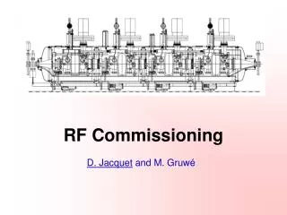
RF Commissioning
RF Commissioning. D. Jacquet and M. Gruw é. RF systems in a few words (I). A transverse dampers system ACCELERATING SYSTEM 4 HV bunkers containing : the klystron modulators the fast protection systems (crowbars) the high voltage switches and the klystron heater power supplies.

RF Commissioning
E N D
Presentation Transcript
RF Commissioning D. Jacquet and M. Gruwé
RF systems in a few words (I) • A transverse dampers system ACCELERATING SYSTEM • 4 HV bunkers containing: • the klystron modulators • the fast protection systems (crowbars) • the high voltage switches • and the klystron heater power supplies. • 16 high power lines : • HV cables, klystron, circulators, RF load, wave guides and the high power couplers • 16 superconducting cavities: • 8 per beam on each side of point 4, powered independently by the high power lines. • Low level RF system… D. Jacquet and M. Gruwé
RF systems in a few words (II) • A sophisticated low level RF system(called cavity controller) • For each RF line: • RF Feedback • a Tuner Loop • a Klystron Ripple Loop • and a Conditioning system => RF control for each cavity is independent. • A beam Control system (generates the 400MHz signal for the cavity controllers) • For each ring: • Frequency Program • Phase Loop • Radial Loop • and Synchronization Loop • An RF synchronization system implements the bunch into bucket transfer from the SPS into each LHC ring. D. Jacquet and M. Gruwé
RF cryo • 4 superconducting cavity modules made of four cavities. =>The temperature of all four cavities in a module is not controlled independently. Each superconducting cavity module is connected to the QRL (4.5K). D. Jacquet and M. Gruwé
Tests • Power systems commissioning • Superconducting cavities commissioning • Klystrons & cavities feedback loops • RF synchro & beam control • Transverse Dampers D. Jacquet and M. Gruwé
POWER SYSTEMS COMMISSIONING • The individual high power RF systems have to be set to full power (short circuited). • The klystron power converters switch ON, and HV settings : done. • HV fast protection system, HV switch to individual klystron and klystron modulators : ongoing (one out of 4 is done). • Low level equipment set-up for open loop operation : done • Commissioning and calibration of high RF power equipment (modulator, RF drivers, klystrons, circulators, loads, directional couplers, …) : on going for 8 cavities, for the other 8 their collectors have to be replaced before the commissioning can start. D. Jacquet and M. Gruwé
CAVITIES COMMISSIONING (I) • Can start only when Power Commissioning has been completed • Additional Services needed • Access system operational in “RF test mode” permitting RF in cavities • Cryogenic system commissioning completed (4.5 K): Cavities cooled down and pressure in the QRL headers stabilized, process control and procedures for cavity operation verified • Radiation monitors operational (RAMSES system commissioned) D. Jacquet and M. Gruwé
CAVITIES COMMISSIONING (II) • Low power verification and measurements: • Couplers and antennas. • Controls: • Check the interlock, signal acquisition, analog multiplexers • Check the cavity tuning system and main couplers positioning system • Set up the control for coupler and cavity conditioning: feedback loops on cavity and main coupler vacuums, He pressure • Tune the RF power with cold cavities. • Pre-calibration measurements: • Antenna/Couplers/Klystrons/Tuners • Conditioning of • the high power couplers up to full power • and the cavities up to full field • Setting up of the tuning loop for each individual cavity D. Jacquet and M. Gruwé
CAVITIES COMMISSIONING (III) • Conditioning of the cavities (cleaning of the cavity surface): • A software (Labview) has been developed to automate the conditioning process: The cavity field is raised by small steps for different position of the couplers, until there is full power and full field in the cavities. • At this stage, operation team may be involved as the cavities can be conditioned in parallel and the procedure is automatic. • The conditioning of the cavities in sector 4-5 will start as soon as the cryo is ready. • The duration off the test is heavily linked to the cryo stability. Without cryo problem, it should take 1 week to prepare the cavities and one week/cavity for the conditioning. D. Jacquet and M. Gruwé
KLYSTRONS & CAVITIES FEEDBACK LOOPS D. Jacquet and M. Gruwé
KLYSTRONS & CAVITIES FEEDBACK LOOPS • The remaining Low-Level RF activity can be carried-out only after the cavities and the main couplers in a module have been conditioned. • For each of the 16 RF lines, the following tests have to be performed • Fine setting up of the tuner loop • Setting up the klystron polar loop (reduces klystron phase ripples) • Setting up the gain, notch and time constants of the RF feedback loop • Setting up the one turn feedback loop • Fine tuning of the "Switch/Protection module" threshold so that we do not trip the klystron on drive transients • A full set of measurements: loop responses etc. • All the above depend on the actual loop delay, klystron response, cable/antenna attenuation so that they have to be customized for each line. D. Jacquet and M. Gruwé
KLYSTRONS & CAVITIES FEEDBACK LOOPS • This tests require a very specific expertise: it is not likely that OP could provide any help. The needed software will be provided by the RF team, probably using Labview. • 2 weeks per cavity are needed • Once all lines are commissioned, a global low-level adjustment will be performed(1 week). D. Jacquet and M. Gruwé
RF SYNCHRO & BEAM CONTROL I • RF synchro : • Generation of kicker pulses, beam dump signals, Frev, clocks to the experiments and the SPS • All hardware modules are ready. They have to be tested as far as possible without beam. • The tests will start mid-January. Expected to last 8 weeks. They have to be completed 3 months before beam. • Beam control : • Set up the 400 MHz reference generation in the Beam Control crate to drive the Cavity Controllers • Commission frequency Prgm, synchro loop, radial loop and phase loop without beam • 2 modules are still under design. • Tests done from March 2008 till beam start up. D. Jacquet and M. Gruwé
RF SYNCHRO & BEAM CONTROL II • These systems are located in SR4, so accessible even during beam. Most of the commissioning will be done with beam. • The commissioning has to be done by the expert who designed the systems. D. Jacquet and M. Gruwé
LHC LLRF RF Synchronization ( from P. Baudrenghien) This is the Dual Freq Program represented on the previous block diagram By changing the programmable delay in the bucket selector one chooses the LHC bucket for transfer This divider will adjust the relative position of ring 2 vs ring 1 This module generates the pulses sent to the injection kickers D. Jacquet and M. Gruwé
LHC LLRF Beam Control ( from P. Baudrenghien) A function sets the RF frequency on the injection plateau and through the ramp Injection frequency, injection phase and stable phase will be adjusted by observing these two signals The VCXO generates the RF sent to the Cavity Controllers This synthesizer replaces the frequency program during physics D. Jacquet and M. Gruwé
TRANSVERSE DAMPERS (ADT) • Principle: • Designed to damp the transverse oscillations of the beam at injection to preserve beam size • The system measures the transverse position of the beam (both horizontal and vertical) and applies a correction • System consists of 4 independent damper systems (2 per beam) with • 4 kickers per beam and plane • Dedicated pickups (2 per plane and per beam) • Electronics on surface (driver amplifiers, PLC controls, fast interlocks) D. Jacquet and M. Gruwé
Overview of one ADT system Commissioned D. Jacquet and M. Gruwé
Damper system IP4 Beam 1 Beam 2 H H V H V H H H V H V H H H V V “Electrostatic” kicker Wideband amplifier Unit • 20 electrostatic kickers • 40 wideband amplifiers, i.e. 40 tetrodes (RS2048 CJC, 30 kW) 20 amplifier cases + V V V V Spare units Module ADT (high power part) D. Jacquet and M. Gruwé
ADT Commissioning • Commissioning: • Controls: Interlocks, power supply controls, application software. Done. • Power converter tests: interlocks, switch ON. Done. • Damper power: Done. • Damper tetrodes power amplifiers • Kickers • Drive amplifiers • Damper Low Level system: feedback loops and the pickups. Ongoing. • One of the card is not completed yet. • Calibration will be finished as soon as card is ready (one month before beam start up) • 10 systems of pick-up have to be calibrated. This requires an access, 2 days per system is needed. • Some work can be done with simulated beam, but most of the setting up requires beam. D. Jacquet and M. Gruwé
Conclusions • RF systems commissioning • The RF power commissioning is ongoing • Once the lines are ready, the cryo in sector 4-5, then in sector 3-4, have to be ready to start the cavities conditioning. • OP can be involved in the cavity conditioning, but the other systems require too much expertise. • The software needed for the hardware commissioning will be provided by the RF group itself. • An operational application has still to be developed, this one should be used for the cold check-out. D. Jacquet and M. Gruwé