RF Cavity Design: Superfish Overview by Ciprian Plostinar
220 likes | 419 Vues
Learn RF cavity design criteria, figures of merit, and examples like pill-box and elliptical cavities. Understand the importance of Superfish for RF cavity designing.

RF Cavity Design: Superfish Overview by Ciprian Plostinar
E N D
Presentation Transcript
RF Cavity Design with Superfish Oxford – John Adams Institute 20 November 2009 Ciprian Plostinar
Overview • RF Cavity Design • Design Criteria • Figures of merit • Introduction to Superfish • Examples: • Pill-box type cavity • DTL type cavity • Elliptical cavity • A low frequency cavity for the proton driver RF compressor (hint: your project!)
RF Cavity Design • In most particle accelerators (except the betatron), the energy is delivered to the particle by means of a large variety of devices, normally know as cavity resonators. • The ideal cavity is defined as a volume of perfect dielectric limited by infinitely conducting walls (the reality is a bit different). • Hollow cylindrical resonator excited by a radio transmitter - > standing wave -> accelerating fields (the pillbox cavity).
RF Cavity Design- Design Criteria - • Define the requirements (intended application), RF frequency, NC/SC, voltage, tuning, etc. • General design criteria: • Power Efficiency & RF Properties • Beam Dynamics considerations (control of loss and emittance growth, etc.) – especially true for linacs • Technologies and precisions involved • Tuning procedures (frequency, field profile, stability against perturbations) • Sensitivity to RF errors (phase and amplitude) • Etc.
RF Cavity Design- Figures of Merit - The Transit Time Factor, T While the particle crosses the cavity, the field is also varying -> less acceleration -> the particle sees only a fraction of the peak voltage -> T is a measure of the reduction in energy gain cause by the sinusoidal time variation of the field in the cavity.
RF Cavity Design- Figures of Merit - The Quality Factor, Q To first order, the Q-value will depend on the conductivity of the wall material only High Q -> narrower bandwidth -> higher amplitudes But, more difficult to tune, more sensitive to mechanical tolerances (even a slight temperature variation can shift the resonance) Q is dimensionless and gives only the ratios of energies, and not the real amount of power needed to maintain a certain resonant mode For resonant frequencies in the range 100 to 1000 MHz, typical values are 10,000 to 50,000 for normal conducting copper cavities; 108 to 1010 for superconducting cavities.
RF Cavity Design- Figures of Merit - Effective Shunt Impedance per unit length Typical values of ZT2 for normal conducting linacs is 30 to 50 M/m. The shunt impedance is not relevant for superconducting linacs. Shunt Impedance - a measure of the effectiveness of producing an axial voltage V0 for a given power dissipated
RF Cavity Design- Figures of Merit - r/Q measures the efficiency of acceleration per unit of stored energy at a given frequency It is a function only of the cavity geometryand is independent of the surface properties that determine the power losses.
RF Cavity Design- Figures of Merit - The Kilpatrick limit High Field -> Electric breakdown Maximum achievable field is limited
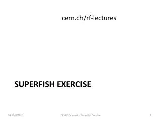
Introduction to Poisson Superfish • Poisson and Superfish are the main solver programs in a collection of programs from LANL for calculating static magnetic and electric fields and radio-frequency electromagnetic fields in either 2-D Cartesian coordinates or axially symmetric cylindrical coordinates. • Finite Element Method • Solvers: • Automesh – generates the mesh (always the first program to run) • Fish – RF solver • Cfish – version of Fish that uses complex variables for the rf fields, permittivity, and permeability. • Poisson – magnetostatic and electrostatic field solver • Pandira – another static field solver (can handle permanent magnets) • SFO, SF7 – postprocessing • Autofish – combines Automesh, Fish and SFO • DTLfish, DTLCells, CCLfish, CCLcells, CDTfish, ELLfish, ELLCAV, MDTfish, RFQfish, SCCfish – for tuning specific cavity types. • Kilpat, Force, WSFPlot, etc.
Poisson Superfish Examples- A Pillbox cavity - • The simplest RF cavity -> Resonant frequency independent of the cell length -> Example: a 40 MHz cavity (PS2) would have a diameter of ~ 5.7 m -> In the picture, CERN 88 MHz For the accelerating mode (TM010), the resonant wavelength is: x1 - first root of the zero-th order Bessel function J0 (x)
Poisson Superfish Examples- A Pillbox cavity - Superfish input file
Poisson Superfish Examples- A DTL-type cavity - • Drift Tube Linac Cavity CERN Linac4 DTL prototype Special Superfish input geometry
Poisson Superfish Examples- A DTL-type cavity - Solution Geometry file Superfish input file
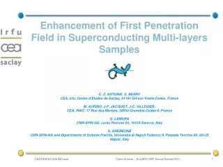
Poisson Superfish Examples- An elliptical cavity - • Often used in superconducting applications INFN & CEA 704 MHz elliptical SC cavities Special Superfish input geometry
Poisson Superfish Examples- An elliptical cavity - Geometry file Superfish input file Solution 1 Cell Solution 5 Cell Cavity
Poisson Superfish Examples- The ACOL Cavity - • A 9.5 MHz cavity for bunch rotation in the CERN Antiproton Collector. • Low Frequency Pillbox-type cavities are challenging because of their large dimensions • Alternatives: • Ferrite Dominated Cavities (Bias current in the ferrite -> Small cavity & Tuning, Typical gap voltage ~ 10 kV, Long beam line space required for higher voltages) • High gradient magnetic alloy loaded cavity (70 kV) • Oil loaded, Ceramic gap loaded cavity
Poisson Superfish Examples- The ACOL Cavity - • Air-core RF cavity: large capacitive electrode -> lower frequency Different models ACOL Cavity Initial Design ACOL Cavity Final Model (Built)
Poisson Superfish Examples- The ACOL Cavity - • Pillbox Cavity, • 2.5/1.64m • f= 91.8 MHz • Pillbox Cavity, • with drift nose • 2.5/1.64m • - f= 56 MHz • Pillbox Cavity, • with one electrode • 2.5/1.64m • - f= 12 MHz • Pillbox Cavity, • with two electrodes • 2.5/1.64m • - f= 9.23 MHz