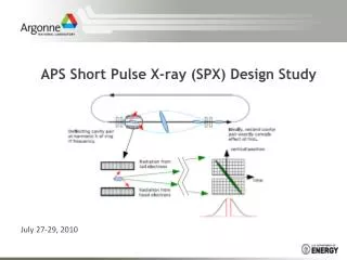
SPX Cavity Design
SPX Cavity Design. Geoff Waldschmidt July 27, 2010. APS / SPX Team JLAB / SRF Institute LBNL / Center for Beam Physics. Single-Cell SC Cavity. Input Coupler. Baseline. HOM Damper. HOM Dampers. LOM Damper. Alternate. Parameters for the Baseline Cavity. Cavity Deflecting Mode.

SPX Cavity Design
E N D
Presentation Transcript
SPX Cavity Design Geoff Waldschmidt July 27, 2010 APS / SPX Team JLAB / SRF Institute LBNL / Center for Beam Physics
Single-Cell SC Cavity Input Coupler Baseline HOM Damper HOM Dampers LOM Damper Alternate Parameters for the Baseline Cavity
Cavity Deflecting Mode LOM coupling to deflecting mode TM110 dipole mode TE20 coupling mode to LOM damper waveguide Electric Field Vector Surface Magnetic Field
Longitudinal and Transverse Impedance Monopole Impedance Vertical Dipole Impedance Stability Threshold Stability Threshold Rt (Ohms / m) Monopole Stability Threshold Horizontal Dipole Impedance Stability Threshold Rt (Ohms / m) Dipole Stability Threshold Horizontal dipole Vertical dipole
Damper Design Concept Each SPX cavity must extract kW’s of HOM/LOM beam power JLAB: Low-power damper testing Plot of E-field vector and dielectric power loss density Slimmer dielectrics: (1) Reduced thermal gradient, (2) Better low-freq performance (3) Reduced high-freq performance APS SPX Concept SiC: epsr=12.8, lossTan=0.37 Return loss: LOM damper SiC lossy dielectric F. Marhauser. “Investigations on Absorber Materials at Cryogenic Temperatures” G. Chang: High-Power Damper Concept
Impedance Response with Dampers and Wg Bends Baseline Cavity with Vertical Wg: GdFidl model Ideal Port SiC dampers SiC: epsr=22 lossTan=0.22 HOM Wg fc=2.09GHz fc = 2.94GHz fc=3.38GHz / . 4.41 GHz HOM wg return loss (no dampers)
RF Loading of Dampers Voltage response in cavity due to beam fill pattern Normalized Cavity Voltage • Qext is typically damped below 1000. • All ports are assumed to be ideal waveguide ports. • 24 bunch fill pattern has been assumed • Non-physical modes due to finite simulation volume have not yet been removed. Power loss spectrum for 24 bunch fill pattern Qext vs. Frequency Time (ns) Normalized Power Loss Qext Normalized Power (W/Ohm) Rt (Ohms/m) Rt (Ohms/m) Long. impedance spectrum Frequency (GHz) Frequency (GHz) Frequency (GHz) Frequency (GHz) Sang-Ho Kim, “HOM power in Elliptical SC cavities for Proton Accel,” NIM A 2002
RF Loading of Dampers (II) (Preliminary) Loss calculated up to 3.5 GHz Total Power Loss (Q=1000) Total Power Loss (Q=100) Total power loss is 3550 W Total power loss is 1900 W • If losses are sufficiently low in HOM dampers, they may be cooled at 80K. • Broadband loss calculated with the loss factor is 3.75kW for 24 bunch mode at 200mA. • Above estimates are too low. Broadband loss should match losses for Q=100 case above. • Losses in dampers are dependent on which modes in eigenmode simulation are considered to be ‘real’. Damper Loss (W) Damper Loss (W) Frequency (GHz) Frequency (GHz) Power Loss (Q=1000) in HOM Damper Total power loss is 43.5 W Damper Loss (W) Frequency (GHz)
Alternate vs. Baseline Baseline • Alternate Benefits • Larger stability margin for 200 mA beam current. • Single excited LOM plus two LOM waveguides produce less rf loading of dampers • More compact • Alternate Disadvantages • Helium vessel more complicated (discussed later) • Additional waveguide penetration for second LOM waveguide • Unproven design features • Magnetic field enhancement? Numerical results show adequate damping without enhancement • Multipacting enhancement? Experimental and numerical results do not show a problem Difficult to Damp: TM110-x mode Alternate Greater stability margin
2-cell Cavity Design Concepts Field enhancement • Multicell cavities have a substantially improved packing factor, as well as reducing the total number of rf systems required. • Same passband modes are difficult to damp without affecting the operating mode. • 2-cell TM110 cavity operating in the pi-mode suffers from magnetic field enhancement on the iris - little net operating gradient improvement. • 2-cell TM110 cavity operating in the 0-mode requires a ‘drift’ space between cells. • Difficult to damp same passband pi-mode due to field configuration in ‘drift’ space and waveguide cutoff frequencies. • Impedance of pi-mode must be reduced to below 4.5 MOhm/m. This can only be achieved by reducing the R/Q to a value below 1e-4 (Qu=~109). Pi-mode Pi-mode cavity Minimal damping Pi-mode 0-mode cavity
2-1/2 Cell Cavity and Cavity Superstructure Concepts 0-mode for 5-cell cavity • 2-1/2 cell Cavity • Center cell is used to couple the SPM into vertical damping waveguide. • 2 pi / 3 mode is not damped in the center cell and is utilized as the operating mode. • Difficult to manufacture and process center geometry. • 5-cell Superstructure • Frequencies of the undamped dipole modes must be located in a stable region of APS spectrum, if this is possible. • Any number of cavity cells may be utilized in a multi-cell if undamped modes can be properly located. SPM Impedance Spectrum Electric field pattern for the operating mode Courtesy: H. Wang, JLAB
Multipacting Simulation extended for 50 rf cycles • 3-D SLAC ACE3P codes were used – already benchmarked extensively against LHC, SNS, and JLAB cavities and couplers. • For deflecting cavities, multipacting is prevalent in low electric field regions near the beam pipe. • Proof-of-principle on-cell damper design was evaluated • Multipacting profile is similar for both baseline and alternate cavity designs In Nb, multipacting may occur at emission energies > 25 eV and < 1.5 keV Deflecting mode electric field magnitude in Omega3P
Lorentz Force Detuning • Detuning was calculated as 10.5 kHz/MV2. • LFD always reduces the resonant frequency. • Structural enhancements may be used to improve response. • Result will be compared with experimental data once the prototype is completed. • LFD of SPX single-cell cavity is 7.9 – 10.5 kHz/MV2 depending on structural constraints. Detuning due to LFD value of 10.5 kHz/MV2 Radiation pressure
Cryomodule Parameters Preliminary Estimate of 2K Losses Estimated System Parameters
JLAB Cryomodule Concept 1-D thermal analysis of beam pipe • Based on JLAB cylindrical cryomodule design. • Dampers are located in vacuum shield of cryomodule - similar to JLAB’s ampere-class cryomodule concept. • Blade tuner located around helium vessel chosen for concept • 1-D analysis of losses along beam pipe from cavity to room temperature estimated 0.26W at 2K with optimized lengths. Courtesy: J. Henry, JLAB G. Cheng, JLAB
Helium Vessel Concepts Helium vessel cut-away • Helium vessel plates are integral with cavity end groups and utilize existing Nb material during construction. • Thermal properties of ‘uncooled’ outer portion of end groups must be analyzed. • Warm ceramic window shown on waveguide input coupler. • Each helium vessel is fed individually by supply lines and a gas return pipe. Helium vessel with waveguides and tuner rings Courtesy: M. Givens, ANL and J. Henry, JLAB
Tuner Options TESLA SNS Soleil (1) P. Bosland ,”Tunings systems for superconducting cavities at Saclay”. (2) C. Pagani, “Improvement of the Blade Tuner Design for Superconducting RF Cavities”.
SPX Tuner Requirements sMax = 17.6 kgf / mm2 > sa • Evenly applied axial pressure of ±1300 N along Y-end group plate produces a 500 kHz tuning range. • Cavity should always be under compression in order to avoid “dead spot” in tuning. A 4000N force creates a 1.5MHz frequency offset. • Peak stress is located along narrow racetrack dimension => 30 MPa KEK 500MHz Crab Cavity sa = 8.1 kgf / mm2 or 79 Mpa according to KEK Titanium bellows Nb plate Uniform pressure:1300 N 30.7 Mpa peak stress
Input Coupler Concept @ 1.5 GHz (JLAB) Dog-leg bend for radiation protection B. Rimmer, “JLAB High-Current Cryomodules,” ERL07
T2 T2 ID VC P P Deflecting Cavity Cromodule Overall Length 8000 mm ?? mm 190 mm 190 mm 2920 mm Space available for cryo-modules + bellows + … 107.3 mm V T1 B B B T1 V Gate valve Bellows Bellows 300 mm Thermal intercept 8 cavities 2750 mm Courtesy: L. Morrison
Field Decay Between Cavities 2 baseline cavities separated by 3 λ/2 3 λ/2 • TM110 cavity fields couple to the low-order TE11 beampipe mode and therefore attenuate more slowly. • Analytical electric field attenuation between cavity assemblies located 3 λ/2 (160mm) apart is 2*10-3, or 53 dB. • Electric field values shown in the line plot show poorer attenuation in addition to coupling to the neighboring cavity. (2) (1) Cavity on the left is OFF Electric Field (Mag) Plot extent shown in figure above Z (mm)
Copper Prototypes at JLAB / ANL Copper single-cell cavity with beampipe LOM damper Copper 2-1/2 cell cavity with damper waveguides and input coupler • Analyzed deflecting frequency and quality factor. • Evaluated LOM / HOM spectrum. • Validated simulation results. • Verified LOM damper effectiveness across frequency range below beam cutoff.
Nb Prototypes at JLAB • Prototyped cavities at JLAB • Created cavity dies • Performed trimming and EB welding. • Performed chemistry processing and HPR • Cavities at 2K for Q, maximum field, and Lorentz force detuning Niobium 2-cell cavity Niobium single-cell cavity Niobium single-cell cavity with on-cell damper Courtesy H. Wang / R. Rimmer
Experimental Results of Nb cavities at JLAB Q vs. Bs single-cell • Unloaded Q has been tested for single-cell and 2-cell cavities without damping waveguides at ~109. • LFD for free-hanging case where one beam pipe is constrained ~15kHz / MV2. • Baseline single-cell cavity with input coupler and HOM/LOM dampers is preparing to be tested in the vertical test stand. Q vs. Bs 2-cell Lorentz Force Detuning (free-hanging) *Courtesy of H. Wang / R. Rimmer
JLAB Continuing Collaboration • Design of cylindrical cryomodule will be pursued with Joel and JLAB cryomodule engineers. • Vacuum vessel, magnetic / thermal shielding, thermal intercepts, space frame layout. • Helium vessel design and layout • Cavity and cavity string alignment techniques • Helium distribution / end caps • ANL may acquire an existing JLAB cryomodule for In-Storage Ring test at the APS • Design of thermal transitions from 2K/80K to room temperature will be pursued between ANL / JLAB mechanical engineers • Waveguide input coupler / dampers • Beam pipe transition • Supports / mounting hardware / tuner • Thermal simulation of helium vessel concept for validation. All collaboration efforts are dependent upon the determination of available resources (personnel and hardware)
JLAB Continuing Collaboration • Cavity design improvements, esp. damping and decision of final cavity to be done by Geoff and Haipeng. • 2K testing in Vertical Test Area (VTA) at JLAB • Must share time with existing obligations to ILC, Project X and RIA. • Manufacture and testing in the VTA for the SPX baseline and alternate designs are slated for the coming months. • Future prototypes and availability must be determined. • Low-power damper testing of SiC at JLAB. High-power design and testing to be done at ANL. • Possible ANL redesign of JLAB input coupler window for 2815 MHz.
Workshop Issues • Cavity • Peak field gradient • Damping enhancement of LOM and TM110-x for baseline design • Baseline and alternate design options (multicell?). • Separation distance between cavities • Frequency tuning from warm to cold for 2.8154872 GHz. • Dampers • SiC or ferrite material • High-frequency damping > 5 GHz important? • High-power design possibilities • Locate inside cryo vacuum or outside: LOM / HOM dampers • Should damper loads with ceramic windows be considered for clean assembly • Input Coupler • Ceramic window design for input coupler • Double warm window • Locate window after a waveguide bend or jog to protect it from radiation • Multipacting analysis • Tuner • End-mount or Blade (SNS / Soleil / Tesla …) • +/- 200kHz? • Fast tuner necessary?