MICE RF System - Status
MICE RF System - Status. Alan Bross Fermilab. RF Cavities for MICE I . Eight 201-MHz cavities in the MICE cooling channel First five cavities arrived at LBNL last year and have been measured Second batch of five cavities will be complete by Oct. 2010 . RF Cavity Design Parameters.


MICE RF System - Status
E N D
Presentation Transcript
MICE RF System - Status Alan Bross Fermilab
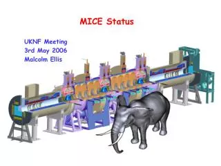
RF Cavities for MICE I Eight 201-MHz cavities in the MICE cooling channel • First five cavities arrived at LBNL last year and have been measured • Second batch of five cavities will be complete by Oct. 2010 MICE Project Board September 23, 2010 Alan Bross
RF Cavity Design Parameters • The cavity design parameters • Frequency: 201.25 MHz • β = 0.87 • Shunt impedance (VT2/P): ~ 22 MΩ/m • Quality factor (Q0): ~ 53,500 • Be window diameter and thickness: 42-cm and 0.38-mm • Nominal parameters for MICE and (cooling channels) in a neutrino factory or muon collider • 8 MV/m (~16 MV/m) peak accelerating field • Peak input RF power: 1 MW (~4.6 MW) per cavity • Average power dissipation per cavity: 1 kW (~8.4 kW) • Average power dissipation per Be window: 12 watts (~100 watts) MICE Project Board September 23, 2010 Alan Bross
NCRF Cavity for Muons • Cavity has been tested successfully without magnetic fields • Be windows can withstand high RF power in strong magnetic field without damage MICE Project Board September 23, 2010 Alan Bross
RF cavities for MICE III • Production of the second batch of five MICE cavities going well at Applied Fusion Company in California • Nose rings • Port extruding and flanges • Brazing water cooling tubes • Modified extruding technique • Experimented using the test cavity • Need argon gas purge to prevent • oxidation of cavity surface • Measure oxidation layer thickness MICE Project Board September 23, 2010 Alan Bross
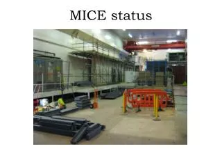
The RF Cavity at LBNL MICE Project Board September 23, 2010 Alan Bross
CMM Scans of MICE Cavity • Special probe to measure the inside profile of the cavity • Cavity interior profile being measured with special probe • ( 1,800 points per scan) • The profile will be used to verify cavity RF models MICE Project Board September 23, 2010 Alan Bross
RF Measurements, Results S11 measurements S21 measurements MICE Project Board September 23, 2010 Alan Bross
Measurement Results • Two cavities have been measured in different window configurations using Be windows #1 and #2 • MICE cavity #1: S21 measurements (2 probes) with all ports shorted: Q 44,000 – 44, 600 (over 80% of the design Q) • MICE cavity #4: S21 measurements (2 probes) with all ports shorted: Q 43,600 – 44, 000 (over 80% of the design Q) MICE Project Board September 23, 2010 Alan Bross
RF Cavity Electro-polishingNext Crucial Step • The inside surface of each RF cavity will be electropolished • Discussions under way with local company Electro-polish tank dimensions: 12' Long x 5' Wide x 6' Deep Large SS piping weldment at AET MICE Project Board September 23, 2010 Alan Bross
RF Cavity Frequency Tuners • 24 Dynamic Cavity Frequency Tuners per Module • Tuner Actuator • Tuners operate in a bi-directional “push - pull” mode (±2mm) • Tuning automatically achieved through a frequency feedback loop MICE Project Board September 23, 2010 Alan Bross
Cavity Frequency Tuner Components • Tuner/actuators are thermally independent of the vacuum vessel • Dual – action actuator • Actuator is • screwed into • the tuner arm • Flexure • tuner arm • Fixed • connection • Forces are transmitted to the stiffener ring by means of “push-pull” loads applied to the tuner lever arms by the dual action actuator assembly MICE Project Board September 23, 2010 Alan Bross
RF Cavity Frequency Tuner Progress Summary • Tuner design is complete • ¼ scale model has been fabricated to test flexure concept • One full size tuner arm (for testing the system) has been fabricated • Aluminum test cylinder (1/6 of cavity) has been fabricated • Actuator mechanical components have been fabricated • Actuator bellows have been delivered to LBNL • Assembly of an actuator has begun at LBNL • Control system components have been delivered to LBNL MICE Project Board September 23, 2010 Alan Bross
Cavity RF Coupler • Section view of cavity RF coupler • Based on successful SNS design with a Toshiba window • Detailed fabrication drawings of the major components are complete MICE Project Board September 23, 2010 Alan Bross
Cavity RF Coupler Design Summary • Detail drawings of major components are complete • Sources for fabrication materials (e.g. 4” outer coax tube) have been identified • Assembly method has been determined MICE Project Board September 23, 2010 Alan Bross
Schedule Summary MICE Project Board September 23, 2010 Alan Bross
RF Power Systems MICE Project Board September 23, 2010 Alan Bross
RF system components Master Oscillator Controls etc DL Test System At present Not found 300 kW Amplifier 300 kW Amplifier 300 kW Amplifier 300 kW Amplifier Auxiliary Systems Auxiliary Systems 2 MW Amplifier 2 MW Amplifier HT Supplies 2 MW Amplifier 2 MW Amplifier HT Supplies Daresbury LBNL CERN 201 MHz Cavity Module 201 MHz Cavity Module
Amplifier status • First medium power (300kW) amplifier and power supply system tested 2008 • Refurbishment and rebuild of first high power (2MW) amplifier complete October 2009 • Power supplies for first 2MW amp 95% complete • Two further 300kW amplifiers awaiting repair • Two refurbished 2MW CERN amplifiers partly tested, awaiting assembly and high power test • Still need to build 3 more sets of power supplies • One more 300kW amplifier to buy/acquire
Hall design in progress • Working with 3D CAD engineer to plan layout between the amplifiers and cavities • Measurements of system dimensions at Daresbury have been taken • First step is a simple block diagram showing all components and how they are interconnected • Then understand how to optimise components with the layout of the hall and the space available • Result will be a complete parts list required for each cavity that we can go out for tender for when appropriate
Future plans for this year • Test of first large amplifier is priority - expected this month • Amplifier testing likely to take 4 – 6 weeks to optimise the system using old tubes, then replace with new MICE tubes and repeat tests carefully • Assembly of the first CERN amplifier, refurbished unit however many small parts, CERN have offered to send two people for a few days to aid with the assembly of the unit – we will take up this offer • Would need to buy more coax components to test this amplifier in our system – coax bends, straights and a combiner • Test of CERN amplifier scheduled for March 2011 • First amplifier will be delivered and installed in the MICE hall
Conclusion • Complete RF amplifier system ready for test, results expected by end September • Design of hall components between amplifiers and cavities is in progress and will lead to a formal design of the coax system, how it will be supported and the sequence of installation • Funding will allow building of CERN amplifier and possible refurbishment of other LBNL amplifier systems
RF Test Facility • MuCool Test Area (MTA) • RF power • 201 MHz (5MW) • 805 MHz (12 MW) • Class 100 clean room • 4T SC solenoid • 250W LHe cryo-plant • Instrumentation • Ion counters, scintillation counters, optical signal, spectrophotometer • 400 MeV p beam line MICE Project Board September 23, 2010 Alan Bross
The RF Challenge • Significant degradation in maximum stable operating gradient with applied B field • 805 MHz RF Pillbox data • Curved Be windows • E parallel B • Electron current/arcs focused by B • Degradation also observed with 201 MHz cavity • Qualitatively, quite different MICE Project Board September 23, 2010 Alan Bross
805 PillboxPost-Mortem • Significant damage observed • Iris • RF coupler • Button holder • However • No damage to Be window MICE Project Board September 23, 2010 Alan Bross
201 MHz Cavity TestTreating NCRF cavities with SCRF processes • The 201 MHz Cavity – Achieved 21 MV/m • Design gradient – 16MV/m • At 0.75T reached 10-12 MV/m However, No observed damage! MICE Project Board September 23, 2010 Alan Bross
201 MHz Cavity RunningSpark Data B=0 Running Design Gradient MICE Gradient MICE Project Board September 23, 2010 Alan Bross
201 MHz Prototype Note: Stored energy available to sparks » 100J (100X that of 805) MICE Project Board September 23, 2010 Alan Bross
Coupler Ceramic TiN Coated Ceramic MICE Project Board September 23, 2010 Alan Bross
201 MHz Cavity B Field TestsSummary • Sparking @ B=0 did condition the 201 cavity • Sparking @ B ¹ 0 causes damage (B relatively low) • Re-conditioned @ B=0. • But upon inspection of the cavity • No observed damage in cavity • SCRF processing techniques help • Some “arcing” evidence on ceramic disk of coupler may be indicative and needs further study • Plan to remove and inspect towards the end of this month MICE Project Board September 23, 2010 Alan Bross
Conclusions • Work on the 201 MHz cavities is well underway and progressing nicely • Although we have seen problems with the 201 prototype operating in B, at MICE gradient (8 MV/m) there appear to be no issues • Coupler damage needs to be investigate • Caveat: Not operated in B of MICE lattice yet! • RF power systems component work is also progressing nicely • Some minor delays due to manpower availability, but have been resolved MICE Project Board September 23, 2010 Alan Bross
Acknowledgements: Derun Li, Steve Virostek (Cavities) Andy Moss (RF Power) MICE Project Board September 23, 2010 Alan Bross
Backup Slides MICE Project Board September 23, 2010 Alan Bross
RF cavities for MICE II • The first five MICE cavities have been measured in three different window configurations using Be windows #1 and #2 (reference windows) • *no water cooling tube brazed to the cavity body MICE Project Board September 23, 2010 Alan Bross
RF measurements, Team Work! Be window installation MICE Project Board September 23, 2010 Alan Bross
RF Cavity Tuner System Schematic MICE Project Board September 23, 2010 Alan Bross
Actuator Design • Actuator design incorporates a sealed enclosure between vacuum and air. • Actuator is mounted to the tuner arm only • Bellows allows angular movement for actuator • Piston plates are joined at the perimeter • Piston plates incorporate hard stops MICE Project Board September 23, 2010 Alan Bross
Cavity RF Coupler Future Work • 16 Toshiba windows (plus spares) need to be ordered soon because of long lead times • Myat RF couplers need to be purchased • Prototype of the outer coax will be fabricated to verify assembly method • Vendor selection process will be started MICE Project Board September 23, 2010 Alan Bross
2MW amplifier summery • Final electrical checks September 2010 – crowbar/cathode modulator systems • Amplifier connected to test load via coax • Water system, air blowers and compressed air have all been on • Filament test to 500A on tube • HT system /earth system checked out and signed off • Safety paperwork needs completing before we power system
Damage to Coupler Ceramic Window? MICE Project Board September 23, 2010 Alan Bross
201 MHz Cavity RunningSummary I (B=0) Limited by RF Power Design Gradient MICE Project Board September 23, 2010 Alan Bross