Download

1 / 19
190 likes | 350 Vues
MICE RF System Overview. Derun Li Center for Beam Physics Lawrence Berkeley National Laboratory Andrew Moss STFC Daresbury Laboratory MICE CM32 @RAL, UK February 8, 2012. MICE RF System Overview. Hardware

E N D
MICE RF System Overview Derun Li Center for Beam Physics Lawrence Berkeley National Laboratory Andrew Moss STFC Daresbury Laboratory MICE CM32 @RAL, UK February 8, 2012
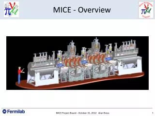
MICE RF System Overview • Hardware • Two RFCC modules: two pairs of four 201-MHz RF cavities with 16 coaxial loop RF couplers and ceramic RF windows (two per cavity) - LBNL • Amplifiers and power distribution systems - DL • Vacuum and water cooling systems - RAL • Diagnostics and control systems • Software • LLRF firmware and cavity tuning • MICE data analysis • Controls and correlation between detectors and RF amplitude/phase • RF design review held in December 2011 Overview of MICE RF system, Derun Li, LBNL, MICE CM32 @ RAL, UK (Feb. 8th 2012)
2 RFCC Modules in MICE Channel RFCC Module #2 RFCC Module #1 Overview of MICE RF system, Derun Li, LBNL, MICE CM32 @ RAL, UK (Feb. 8th 2012)
RFCC Module Overview • The MICE RF and Coupling Coil Module has been designed by LBNL and our collaborators • The MICE cooling channel incorporates two RFCC modules to be provided by LBNL • Each module consists of a single superconducting Coupling Coil integrated with four tunable 201 MHz normal conducting RF cavities and a vacuum vessel • The Coupling Coil design was developed by the Harbin Institute of Technology (HIT) in China (a MICE collaborator), in collaboration with LBNL • A third Coupling Coil (first delivered) for MuCool will be sited in the MTA at Fermilab • The 201 MHz cavity design is based on the prototype cavity developed by LBNL and J-Lab and has been operated in the MTA Overview of MICE RF system, Derun Li, LBNL, MICE CM32 @ RAL, UK (Feb. 8th 2012)
RFCC Module Overview Coupling Coil RF Cavities Tuner arms Couplers Overview of MICE RF system, Derun Li, LBNL, MICE CM32 @ RAL, UK (Feb. 8th 2012)
Status of RF Cavities • Ten RF cavities (two spares) at LBNL now; • All 11 beryllium windows received at LBNL; • Ten ceramic RF windows; • Six tuner flexures are being fabricated at Fermilab; • Components for 6 actuators are being fabricated; • RF loop coupler design has been updated to eliminate the gap between the outer coax and the RF loop; • EP preparation in progress at LBNL: • Fabrication of fixturing complete; • ES &H approval for EP in progress at LBNL; • Preparation of the cavity surface: mechanical smoothing; • EP to start after the ES & H approval. • Measurements of the remaining six cavities to start after EP; • Each cavity willbe tuned to a center frequency after EP. Overview of MICE RF system, Derun Li, LBNL, MICE CM32 @ RAL, UK (Feb. 8th 2012)
Coupler design EP setup at LBNL Be windows at LBNL Wire EDM at FNAL Tuner design Tuner arms fabricated at FNAL Overview of MICE RF system, Derun Li, LBNL, MICE CM32 @ RAL, UK (Feb. 8th 2012)
RF Power System Components Master Oscillator Controls etc DL Test System At present Not found 300 kW Amplifier 300 kW Amplifier 300 kW Amplifier 300 kW Amplifier Auxiliary Systems Auxiliary Systems 2 MW Amplifier 2 MW Amplifier HT Supplies 2 MW Amplifier 2 MW Amplifier HT Supplies Daresbury LBNL CERN 201 MHz Cavity Module 201 MHz Cavity Module Overview of MICE RF system, Derun Li, LBNL, MICE CM32 @ RAL, UK (Feb. 8th 2012)
RF Amplifier Status • Refurbishment of LBNL and CERN RF components: • First medium power (250 kW) amplifier and power supply system tested 2008 • Refurbishment and rebuild of first high power (2 MW) amplifier complete October 2009 • Power supplies for first 2 MW amp operational • Two further 300 kW amplifiers awaiting repair • Two refurbished 2 MW CERN amplifiers partly tested, awaiting assembly and high power test • Need to build 3 more sets of power supplies • One more 300kW amplifier to buy/acquire Overview of MICE RF system, Derun Li, LBNL, MICE CM32 @ RAL, UK (Feb. 8th 2012)
RF Power Distribution Trombone phase shifter Outputs to cavity RF load Hybrid power splitter Overview of MICE RF system, Derun Li, LBNL, MICE CM32 @ RAL, UK (Feb. 8th 2012)
RF Power Distribution Overview of MICE RF system, Derun Li, LBNL, MICE CM32 @ RAL, UK (Feb. 8th 2012)
Current Status/Plan of RF Power Sys. Amplifier test system tested to 1 MW with power supplies; Coax system designed to phase match RF into each cavity, all coax lines are the same length and have the same number of elbows; Hybrids will be used to split RF power and give good isolation, reject load can be small as balanced reflected; power will be directed back to triode, this should not present an issue; Cavity phasing can be done using a combination of LLRF and limited range high power phase shifters; Nitrogen gas pressure will be used to extend the peak voltage stand off of the coax guides. Overview of MICE RF system, Derun Li, LBNL, MICE CM32 @ RAL, UK (Feb. 8th 2012)
High Power Amplifier Reached 1 MW RF power 4616 Medium Power Amplifier Andrew Moss working at DaresburyLaboratory MTA RF setup
Presentations on RF at CM32 • Thursday afternoon, February 9, 2012 • RF Cavities • Derun Li (LBNL) • RF Power • Andrew Moss (Daresbury Laboratory) • RF Control and Monitoring • Chris White (STFC Daresbury Laboratory) • RF US Program • Yagmur Torun (Illinois Institute of Technology) • RF review report and RF Specification • Andrew Moss (Daresbury Laboratory) Overview of MICE RF system, Derun Li, LBNL, MICE CM32 @ RAL, UK (Feb. 8th 2012)
Single Cavity Vacuum Vessel • The design kept as much as possible of • the same dimensions and features of • the RFCC module • One vessel to accommodate two types • of MICE cavities (left and right) • Possible for future LN operation RFCC module Overview of MICE RF system, Derun Li, LBNL, MICE CM32 @ RAL, UK (Feb. 8th 2012)
Single Cavity Vacuum Vessel Status • Design was completed in mid-2011 at LBNL • Fabrication is complete at Keller Technology in • Buffalo New York • The vessel should arrive Fermilab this week Overview of MICE RF system, Derun Li, LBNL, MICE CM32 @ RAL, UK (Feb. 8th 2012)
Testing of theSingle Cavity Vessel • Check engineering and mechanical design • Fully define the fabrication process • Incorporate any design changes into the RFCC vacuum vessel design • Test of the RF tuning system with 6 tuners and actuators on a cavity and verify the frequency tuning range • Obtain hands-on experience on assembly and procedures • Cavity installation • Develop fixturing for inserting the cavities into the vacuum vessel • Beryllium windows • RF couplers and connections • Water cooling pipe connections Overview of MICE RF system, Derun Li, LBNL, MICE CM32 @ RAL, UK (Feb. 8th 2012)
Testing of theSingle Cavity Vessel • Vacuum port and connections • Tuners and actuator circuit • Mounting and alignment of the tuners onto the cavity is critical to alignment of the cavity in the vacuum vessel • Alignment of actuator (through the vacuum vessel wall) to the tuner is important • Aligning cavity with hexapod support struts • Test developed MathCAD alignment software program • Vacuum vessel support and handling • Verify operation of the getter vacuum system • RF processing MICE cavities • RF power system and future LN operation Overview of MICE RF system, Derun Li, LBNL, MICE CM32 @ RAL, UK (Feb. 8th 2012)
Summary and Tasks • Progress in MICE RF hardware development ; • RF design review held in December 2011 (to be reported by A. Moss); • Progress of the LLRF control (A. Moss); • Specification/Interface between RF power system and RFCC modules; • Plan/development for diagnostics and controls, in particular with detector/analysis group: • Communications/meetings started recently at LBNL, but need a real plan • Testing plan of using the single cavity vessel at the MTA, Fermilab • Waiting for cavity EP at LBNL, fabrication of other accessory components; • Assembly and integration; • MICE cavity tuningand control; • Experimental study of high magnetic field at RF coupler region; • Welcome RF testing proposals from MICE collaborators. Overview of MICE RF system, Derun Li, LBNL, MICE CM32 @ RAL, UK (Feb. 8th 2012)