Download

1 / 1
10 likes | 112 Vues
Explore the implementation and performance measurements of DABC Frontend hardware for data acquisition backbone core systems. This study delves into event selection, time distribution, data flow control, and more for efficient functionality.

E N D
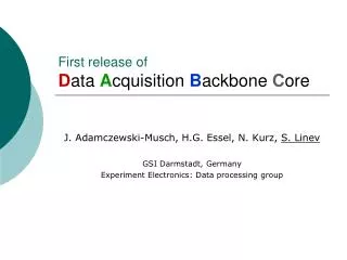
thread Wait Network Interface A memory pool memory pool Network Interface B Input Port Motivation for developing DABC Frontend hardware example Thread with 1-n modules ActionEvent manager Command Data flow control of DABC (event) Device thread DABC Module A processInput processCommand & Queue Transport & Data queue Data ready event Performance measurements InfiniBand DABC as data flow engine FE Front-end board: sampling ADCs (4*4), clock distribution FE *8 2.5 GBit/s bi-directional (optical) link: data, clock DCB Data combiner boards, clock distribution to FE DC Module manager FE: Frontend board DC: Data combiner board DD: Data dispatcher board GE: Gigabit Ethernet IB: InfiniBand *4 2.5 GBit/s data links Data dispatcher board: PCI express card ABB DABC Module DABC Module DD GE switch port process port process PC PCIe 8-20 PCs dual quad PC Process network port port bi-directional event building PC PC IB switch Dataqueue Dataqueue Transport Transport locally Gigabit Ethernet Builder network Network Device Device Memory management Data Acquisition Backbone Core DABC J. Adamczewski, H.G. Essel, N. Kurz, S. Linev GSI, Darmstadt First sketch of the data acquisition concept for CBM (2004) H.G.Essel, FutureDAQ for CBM: On-line event selection, IEEE TNS Vol.53, No.3, June 2006, pp 677-681 The new Facility for Antiproton and Ion Research at GSI All nodes send to all nodes (bi-directional). Data rates are per direction. In synchronized mode senders send data according a time schedule avoiding conflicts at the receivers. Without synchronization all senders send round robin to all receivers and the network must handle collisions. Measurements have been performed at GSI (4 double Opteron machines 2.2 GHz, non synchronized, left graph) and Forschungszentrum Karlsruhe (IWF) on a cluster with 23 double dual-core Opteron (2.2 GHz)* and SilverStorm (QLogic) switch. On the 4 nodes at GSI there is no difference between synchronized and non synchronized mode. The left Figure shows hardware components the DABC has to deal with. Front-end boards typically keep sampling digitizers, whereas combiner and dispatcher boards have fast data links controlled by FPGAs. Prototypes of these boards are under test. Data rates in the order of 1 GBytes/s could be delivered through the PCI express interface. • Use cases • Detector tests • FE equipment tests • High speed data transport • Time distribution • Switched event building • Software evaluation • MBS* event builder • Requirements • build events over fast networks • handle triggered or self-triggered front-ends • process time stamped data streams • provide data flow control (to front-ends) • connect (nearly) any front-ends • provide interfaces to plug in application codes • connect MBS readout or collector nodes • be controllable by several controls frameworks On the IWF cluster the scaling of bandwidth with the number of nodes has been measured from 5 to 23 nodes (right graph). The rates are plotted normalized to 5 nodes (100%). Rates drop to 83% for non synchronized traffic and large buffers. With 8 KB buffers traffic stays at nearly 100%. The fourth measurement shows the effect of synchronizing the traffic: Performance for large buffers on 23 nodes is even better than non synchronized on 5 nodes. Logical structure of DABC • General purpose DAQ • Event building network with standard components like InfiniBand • Scheduled data transfer with ~10µs accuracy • Thread synchronization with determined latency • Needs realtime patches of standard Linux kernel 2.6.19: • RT priorities, nanosleep and pthread_condition • PREEMPT_RT (Ingo Molnar), high resolution timer (Thomas Gleixner) DABC datainput PC frontendReadout Logically such a setup looks like sketched in right Figure. Depending on the performance requirements (data rates of the front-end channels) one may connect one or more front-ends to one DABC node. From a minimum of one PC with Ethernet up to medium sized clusters all kind of configurations are possible. One may separate input and processing nodes or combine both tasks on each machine using bi-directional links depending on CPU requirements. sorting tagging filter analysis frontendMBS readout scheduler frontendother GE IB PC scheduler analysis archive Bandwidth achieved by DABC event building on 4 nodes at GSI (non synchronized mode, left graph). The test measurement result is included for comparison. With buffers > 32KB DABC delivers nearly the bandwitdh of the plain test program. Gigabit Ethernet delivers 70MByte/s. Four data sources per node generate data. Event building on the receiver nodes only checks the completeness of data. sorting tagging filter analysis PC • Using the real time features of Linux • Linux kernel 2.6.19 with RT patches (high resolution timer now in 2.6.21). • With two threads doing condition ping-pong and one "worker"-thread one turn is 3.2 µs • With high resolution timer and hardware priority a sleeping thread gets control after 10 µs. • Synchronized transfer with microsleep achieves 800 MB/sec datainput archive * Muliti Branch System: current standard DAQ at GSI * Many thanks to Frank Schmitz and Ivan Kondov The right Figure shows the components of DABC data flow mechanism. Basic object is a module which gets access to data buffer queues through input ports, processes them, and outputs them to output ports. The data queues on each node are controlled by a Memory management which allows processing buffers without copy by modules running on the same node. The Transport component in this case propagates only references. If a port is connected to a remote port, the Transport and Device components do the transfers. Java GUI (DIM client) wait for buffer add buffer thread Producer Output Port thread Send signal wait allocate send buffer wait completionwait feed back free Network IO IO feed back allocate wait receive free put new buffer Module components can either run in separate threads to utilize multiple CPUs, or in one thread which is faster because no module synchronization by mutexes is needed in this case (left Figure). Data processing functions of the module are called by an Action event manager. The data flow is controlled by buffer resources (queues) handled through the Transports. Once a queue buffer is filled, the Transport sends a signal to the ActionEvent manager, which in turn calls the processInput function of the module associated through a port. This function has access to the data buffers through the port (Fig. above). Similarly, commands can be sent to the ActionEvent manager, which calls the associated module function processCommand. thread Consumer thread Receive add buffer wait for buffer If the receiver nodes are busy with other calculations like event building, it is necessary to hold the senders. This is achieved by the back pressure mechanism shown in Figure above. The receivers inform the senders about their queue status after a collection of buffers. The senders only send when the receivers signalled sufficient resources.The back pressure works smoothly. The GUI is built up dynamically by the information delivered by the DIM servers running in the application threads on all nodes CHEP2007 Victoria BC, Canada, 2- 7 September, 2007 http://www-linux.gsi.de/~dabc/dabc/DABC.php Work supported by EU RP6 project JRA1 FutureDAQ RII3-CT-2004-506078