Download
1 / 26
260 likes | 282 Vues
Learn about AC circuits, AC sources, amplitude, frequency, phase shift, impedance in resistors, capacitors, inductors, and combined circuits, power calculations, and graphical impedance addition in this detailed guide.

E N D
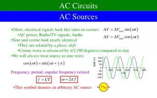
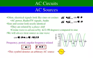
AC Circuits AC Sources • Often, electrical signals look like sines or cosines • AC power, Radio/TV signals, Audio • Sine and cosine look nearly identical • They are related by a phase shift • Cosine wave is advanced by /2 (90 degrees) compared to sine • We will always treat source as sine wave Frequency, period, angular frequency related • This symbol denotes an arbitrary AC source
RMS Voltage • There are two ways to describe the amplitude • Maximum voltage Vmax is an overstatement • Average voltage is zero • Root-mean-square (RMS) voltage is probably the best way • Plot (V)2, find average value, take square root • We can do something similar with current House current (US) is at f = 60 Hz and Vrms = 120 V Vmax = 170 V
Amplitude, Frequency, and Phase Shift We will describe any sort of wave in terms of three quantities: • The amplitudeAis how big it gets • To determine it graphically, measure the peak of the wave • The frequency is how many times it repeats per second • To determine it graphically, measure the period T • Frequency f = 1/T and angular frequency = 2f • The phase shift is how much it is shifted earlier/latercompared to basic sine wave • Let t0 be when it crosses the origin while rising • The phase shift ist0(radians)
Our Goal • Feed AC source through an arbitrary circuit • Resistors, capacitors, inductors, or combinations of them • We will always assume the incoming wave has zero phase shift ? • We want to find current as a function of time • For these components, can show angular frequency is the same • We still need to find amplitude Imax and phase shift for current • Also want instantaneous power P and average powerP consumed • Generally, maximum current will be proportional to maximum voltage • Call the ratio the impedance, Z
Degrees vs. Radians • All my calculations will be done in radians • Degrees are very commonly used as well • But the formulas look different • Probably best to set your calculator on radians and leave it there
Resistors R = 1.4 k • Can find the current from Ohm’s Law • The current is in phase with the voltage VoltageCurrent Impedance vector: • A vector showing relationship between voltage and current • Length, R is the ratio • Direction is to the right,representing the phase shift of zero 1.4 k
Power in Resistors R = 1.4 k • We want to know • Instantaneous power • Average Power
Capacitors C= 2.0 F • Charge of capacitor is proportional to voltage • Current is derivative of charge • Current leads voltage by /2 • We say there is a –/2 phase shift: Impedance vector: • Define the impedance* for a capacitor as: • Make a vector out of it • Length XC • Pointing down for = –½ 1.3 k *We will ignore the term “reactance”
Power in Capacitors C= 2.0 F We want to know • Instantaneous Power • Average Power • Power flows into and out of capacitor • No net power is consumed by capacitor Only resistors contribute to the average power P consumed
Capacitors and Resistors Combined • Capacitors and resistors both limit the current – they both have impedance • Resistors: same impedance at all frequencies • Capacitors: more impedance at low frequencies
Inductors • Voltage is proportional to change in current • Integrate this equation L= 4.0 H • Current lags voltage by /2 • We say there is a +/2 phase shift Impedance vector: • Define the impedance for an inductor as: • Make a vector out of it • Length XL • Pointing up for = +½ 1.5 k
Adding Impedances Graphically • Suppose we have 2+ items in series • Resistors, Capacitors, Inductors • We can get the total impedance and phase shift by adding the impedances graphically 1.4 k 1.4 k 60 Hz170 V The impedance and phase shift of two components in series can be found by adding the vector sum of the two separate impedances • Each impedance is represented by a 1.4 k vector pointing to the right • The length of the combination is 2.8 k • The total impedance is denoted Z • The total arrow is to the right, so phase shift is 0 1.4 k 1.4 k Z = 2.8 k
Adding Impedances Graphically (2) We can add different types of components as well • The resistor is 1.4 k to the right • The capacitor is 1.3 k down • The total is 1.9 k down-right 1.4 k 2.0 F 1.4 k 60 Hz170 V 1.3 k 1.9 k • The current is then the voltage over the impedance • The phase can be found from the diagram
RLC AC Circuits L C R • For this rather general circuit, find • Impedance • Phase shift • Current • Average power f Vmax • Find the angular frequency • Find the impedance of the capacitor and inductor • Find the total impedance Z • Find the phase shift • Find the current • Find the average power consumed XC XL R Z
Power in RLC AC Circuits 6. Find the average power consumed L C R Only resistors contribute to the average power P consumed f Vmax • Most power is delivered to resistor when Imax is maximized • When Impedance is minimized • The “resistor” might well represent some useful device • Like a speaker for a stereo
Frequency and RLC Circuits Low pass filter High pass filter L C • Impedance tends to be dominated bywhichever component has largest impedance • At low frequencies, that’s the capacitor • At high frequencies, that’s the inductor • At intermediate, that’s the resistor • If the circuit includes a capacitor, it blocks low frequencies • If the circuit includes an inductor, it blocks high frequencies R f Vmax
A Sample Circuit 1000 F 0.1 mH 10 f Vmax = 5 V • What frequencies make it through the capacitor? • What frequencies make it through the inductor? • These inequalities compatible if:
A Sample Circuit (2) Power Phase Shift 1000 F 0.1 mH 10 f Vmax = 5 V • At low frequencies, blocked by capacitor • At high frequencies, blocked by inductor • At intermediate, power goes to resistor • Frequencies from about 16 Hz–16 kHz get through • Close to perfect for an audio system What happens if L > R2C ?
The Narrow Band Filter 2.1 pF 1.54 H 2.0 f Vmax = 1 mV • At resonant frequency, capacitor and inductor cancel • Perfect for picking up WFDD – radio station in North Carolina
Types of RLC Circuits High Pass Filter • Lets frequencies through if > 1/RC Low Pass Filter • Lets frequencies through if < R/L RLC circuit • If R2 > L/C, it is a combination of Low and High pass filter • If R2 < L/C it only lets a narrowrange of frequencies through • The smaller R2C/L, the narrower it is
Comments on Phase Shifts • The phase shift represents how the timing of the current compares to the timing of the voltage • When it is positive, the current lags the voltage • It rises/falls/peaks later • When it is negative, the current leads the voltage • It rises/falls/peaks earlier
Transformers N1 turns N2 turns • Let two inductors share the same volume • You can (should) give them an iron core too • The EMF’s can be calculated from the flux • The magnetic flux must be changing • Only works for AC
What Transformers are Good For N1 =500 N2 =5000 V2 = ? V1 = 120 V • Their main purpose in life is to change the voltage A 120 V AC source is fed into a transformer, with N1 = 500 turns on the primary coil, and N2 = 5000 turns on the secondary. What is the voltage out of the transformer? • Voltage can increases, does that mean power increases? • When you increase voltage, you decrease current • In an ideal transformer, the product is conserved Realistic transformers are 80-95% efficient
Transformers and Power Transmission Generator500 V Transmission Line 100 kV House Current 120 V • Why transmit at 10 kV, instead of 500 V or 120 V? • Transmission wires are long – they have a lot of resistance • By using a step up transformer, we increase the voltageand decrease the current • Power lost for a resistor is: • You then step it down so youdon’t kill the customer
Power Supplies 20 Vripply DC 20 Vsmooth DC 21 V AC To devices 120 V AC • What if we need a different voltage for a specific device? • Use a transformer • What if we want direct current? • A diode is a device that only lets current through one direction • What if we don’t like the ripples • Capacitors store charge from cycle to cycle