Download
1 / 23
250 likes | 892 Vues
An Ultra-Wideband CMOS VCO with 3~5GHz Tuning Range. RFIT2005 - IEEE International Workshop on Radio-Frequency Integration Technology, Nov 30-Dec 02, 2005, Singapore. Chien-Cheng Wei, Hsien-Chin Chiu, and Wu-Shiung Feng Department of Electronic Engineering Chang Gung University

E N D
An Ultra-Wideband CMOS VCO with 3~5GHz Tuning Range RFIT2005 - IEEE International Workshop on Radio-Frequency Integration Technology, Nov 30-Dec 02, 2005, Singapore Chien-Cheng Wei, Hsien-Chin Chiu, and Wu-Shiung Feng Department of Electronic Engineering Chang Gung University Taoyuan, Taiwan, R.O.C. 指導教授: 林志明 教授 學 生: 劉彥均
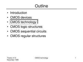
Outline • INTRODUCTION • ARCHITECTURE • CHARACTERISTICS OF TUNABLE ACTIVE INDUCTOR AND UWB VCO • CONCLUSION
INTRODUCTION • Ultra-wideband (UWB):low-frequency band: 3.1-5 GHz; high-frequency band:6-10.6 GHz. • In the VCO design, it is necessary to increase the tuning ranges to guarantee that the desired frequency range is covered. • One way to easily resolve this problem is using some capacitors for the switched tuning elements of the VCO. • The capacitance variation of the varactor is not wide enough. • For increasing the tuning range of the VCO, the tunable active inductor is proposed in the paper.
ARCHITECTUREA. Active Inductor Design(1) • The spiral inductors using the lossy silicon substrate could not easily achieving good performance in CMOS technologies. • Active inductor is based on the "gyrator theory", containing only two transistors.
ARCHITECTUREA. Active Inductor Design(2) • Gyrator theory: 所謂”旋相器”,就是能將”訊號相位”旋轉的電路,假如” Input ”信號的 Voltage/Current 均為同相位,則經過”旋相器”處理後的信號就應該是 Voltage 相位超前 Current 相位 90 度,呈現電感( Inductor )特性
ARCHITECTUREA. Active Inductor Design(4) • The most common one-port active inductor topology (a) Grounded active inductor.
ARCHITECTUREA. Active Inductor Design(5) • For achieving a wider bandwidth, a cascode circuit topology has been proposed to reduce the output conductance (gds). (b) Cascode-grounded active inductor.
ARCHITECTUREA. Active Inductor Design(6) • In order to further enhance the inductance and quality-factor of this active inductor, a feedback resistance Rf hasbeen added between M2 and M3.
ARCHITECTUREA. Active Inductor Design(7) Feedback resistance active inductor. Equivalent circuit
ARCHITECTUREA. Active Inductor Design(8) • The feedback resistance Rf forms an additional inductive reactance of the impedance looking into the source terminal of M2, which can significantly increase the inductance of cascode grounded active inductor. • Furthermore, the increased inductance also results in an increase quality-factor.
ARCHITECTUREA. Active Inductor Design(9) • In equations (I) and (2), by decreasing the equivalent resistance Req with the help from the Rf, also results in an increase of the equivalent inductance Leq. Therefore, the inductance and quality-factor can be improved in consequence. (1) (2)
ARCHITECTUREA. Active Inductor Design(10) • The tunable active resistor has been implemented using a passive poly resistor in parallel with an NMOS. Tunable active resistor topology. Variation of resistance for different tuning voltages.
ARCHITECTUREA. Active Inductor Design(11) • By tuning the resistance Rf, we obtain the control on the inductance value as well as the quality-factor. Variation of inductance for different tuning voltages.
ARCHITECTUREA. Active Inductor Design(12) • The required inductance value with high quality-factor at the required frequency of operation , is achieved by controlling both and simultaneously.
ARCHITECTUREA. Active Inductor Design(13) • In this tunable active inductor, we set the maximum quality-factor at the required frequency 4GHz for the application of low-frequency band 3.1-5 GHz UWB system Maximum quality-factor at the required frequency 4GHz.
ARCHITECTUREB. Active-Inductor-based VCO(1) Schematic of the ultra-wideband CMOS VCO. Circuit layout
ARCHITECTUREB. Active-Inductor-based VCO(2) • According to the Backhouse's criteria, the loop gain of the feedback system must equals to unity, and the total phase shift around the loop equals to zero. • The ratio Ll/L2 determines the feedback factor and thus must be adjusted in conjunction with the transistor gain to ensure that the oscillators will start.
ARCHITECTUREB. Active-Inductor-based VCO(3) • The active inductor generates additional noise that results in a higher noise factor degrade the phase noise in VCO. • Compared to the conventional passive spiral inductors VCOs, active inductor-based VCOs do not show the advantage regarding for phase-noise performance.
CHARACTERISTIC OF TUNABLE ACTIVE INDUCTOR AND UWB VCO(1) • The oscillation frequency of the VCO is around 2.7 to 5.4 GHz with the 2.7GHz tuning range by the controlled voltage from IV to 2.6V.
CONCLUSION • The tunable active inductor generates inductance between 1.7 to 6.3-nH with the quality-factor > 30 by a tunable feedback resistance. • The tuning range of this proposed VCO is approximately from 3 to 5GHz. • Comparisons of this topology with conventional VCO show that this topology achieves better performance with very wide tuning range and compact chip size(0.6mm*0.675mm).