Download
1 / 17
190 likes | 390 Vues
An Ultra-Wide-Band 1.0 -11.6GHz LNA in 0.18µm CMOS technology. RF Communication Systems-on-chip. Spring 2007. Index of Contents. A brief introduction to UWB Potential applications Design of the LNA Performance criteria First stage: a common-gate Second stage: a common-source

E N D
An Ultra-Wide-Band 1.0 -11.6GHz LNA in 0.18µm CMOS technology RF Communication Systems-on-chip Spring 2007
Index of Contents • A brief introduction to UWB • Potential applications • Design of the LNA • Performance criteria • First stage: a common-gate • Second stage: a common-source • System simulation • Comparison with the original paper • Conclusions
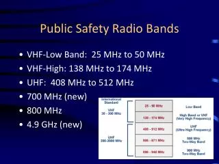
A brief introduction to UWB • A technology for transmitting information spread over a large bandwidth that should be able to share spectrum with other users. • The Federal Communications Commission (FCC) authorized the unlicensed use of the 3.1 to 10.6GHz band under strict power restrictions. OFDM vs. Pulse-transmission
Potential applications 5 • Wireless Communications Systems • Local and Personal Area Networks (LAN/PAN) • Roadside info-station • Short range radios • Military Communications • Radar and Sensing • Vehicular radar • Ground penetrating radar • Through wall imaging • Medical imaging • Surveillance
Performance criteria • As any Low-Noise Amplifier, an UWB LNA should have: • Low noise figure (i.e., below 6dB) • High gain (i.e., above 10dB) • Input matching to 50Ω (i.e., S11 below -10dB) • Output matching to 50Ω (i.e., S22 below -10dB) • But also, with a flat response in the whole 3.1-10.6GHz band.
Circuit description (I) • Two-stage amplifier • The first stage fixes the input impedance of the system and defines a low frequency resonance. • The second stage drives the LNA total gain by fixing a second resonance in the high frequency part of the band.
The common-gate stage Input impedance There is a resonance near DC. At high frequencies, gm1 becomes the dominant term. Circuit description (II) 9 With RL1=320Ω, WM1=55µm and VG1=0.7V,gm1 is in the order of 20mS
The common-source stage Defines a second resonance in the high part of the band. Provides the gain to the system. The output buffer was already given: WM4=55µm and Ibias=5.7mA. Circuit description (III) 10 With RL2=60Ω, WM2=WM3=120µm and VG2=1V, both transistors are still in the saturation region
Circuit simulation (I) 12 • Effect of changing LS1 from 2nH to 10nH • Effect of changing LD2 from 1nH to 3nH Gain (dB) Gain (dB) Taking into account the UWB FCC mask already shown, trying to move the first resonance far below the 3GHz is not necessary.
Circuit simulation (II) 13 • Effect of changing WM2 and WM3 from 40µm to 200µm. • Effect of changing VG2 from 0.6V to 1.6V Gain (dB) Gain (dB) A good compromise between total gain and power consumption is achieved, for example, with 120µm and a VG2 equal to 1.2V.
Design comparison Very similar results have been obtained.
Conclusions • A two-stage LNA amplifier from 1.0 and up to 11.6GHz has been designed. • A common-gate stage fixes the input impedance of the system and creates a first resonance at low frequencies. • A common-source stage drives the system gain and introduces a resonance in the high part of the band. • A nearly flat gain of 13dB and a noise figure of 4dB are achieved within this topology.
Josep Miquel Jornet Montaña [jmjornet@gmail.com] Thank you for your attention RFCS. Spring 2007.