VLSI Technology
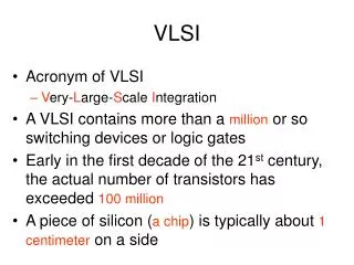
VLSI Technology. Introduction Typical Applications Moore’s Law The cost of fabrication Technology Background What is a chip Fabrication Technology CMOS Technology. VLSI Technology. VLSI is an implementation technology for electronic circuitry – analog or digital


VLSI Technology
E N D
Presentation Transcript
VLSI Technology • Introduction • Typical Applications • Moore’s Law • The cost of fabrication • Technology Background • What is a chip • Fabrication Technology • CMOS Technology Dr VP Dubey VLSI Technology
VLSI Technology • VLSI is an implementation technology for electronic circuitry – analog or digital • It is concerned with forming a pattern of interconnected switches and gates on the surface of a crystal of semiconductor • Microprocessors • personal computers • microcontrollers • Memory - DRAM / SRAM • Special Purpose Processors - ASICS (CD players, DSP applications) • Optical Switches • Has made highly sophisticated control systems mass-producable and therefore cheap Dr VP Dubey VLSI Technology
Moore’s Law • Gordon Moore: co-founder of Intel • Predicted that the number of transistors per chip would grow exponentially (double every 18 months) • Exponential improvement in technology is a natural trend: • e.g. Steam Engines - Dynamo - Automobile Dr VP Dubey VLSI Technology
What is a Silicon Chip? • A pattern of interconnected switches and gates on the surface of a crystal of semiconductor (typically Si) • These switches and gates are made of • -areas of n-type silicon • -areas of p-type silicon • -areas of insulator • -lines of conductor (interconnects) joining areas together • Aluminium, Copper, Titanium, Molybdenum, polysilicon, tungsten • The geometry of these areas is known as the layout of the chip • Connections from the chip to the outside world are made around the edge of the chip to facilitate connections to other devices Dr VP Dubey VLSI Technology
Fabrication Technology • Silicon of extremely high purity • chemically purified then grown into large crystals • Wafers • crystals are sliced into wafers • wafer diameter is currently 150mm, 200mm, 300mm • wafer thickness <1mm • surface is polished to optical smoothness • Wafer is then ready for processing • Each wafer will yield many chips • chip die size varies from about 5mmx5mm to 15mmx15mm • A whole wafer is processed at a time Dr VP Dubey VLSI Technology
Different parts of each die will be made P-type or N-type (small amount of other atoms intentionally introduced - doping -implant) • Interconnections are made with metal • Insulation used is typically SiO2. SiN is also used. New materials being investigated (low-k dielectrics) Dr VP Dubey VLSI Technology
Fabrication Technology • NMOS Fabrication • CMOS Fabrication • -n-well process • -p-well process • -twin-tub process • BiCMOS Dr VP Dubey VLSI Technology
Fabrication Technology • All the devices on the wafer are made at the same time • After the circuitry has been placed on the chip • the chip is overglassed (with a passivation layer) to protect it • only those areas which connect to the outside world will be left uncovered (the pads) • The wafer finally passes to a test station • test probes send test signal patterns to the chip and monitor the output of the chip • The yield of a process is the percentage of die which pass this testing • The wafer is then scribed and separated up into the individual chips. These are then packaged • Chips are ‘binned’ according to their performance Dr VP Dubey VLSI Technology
CMOS Technology • First proposed in the 1960s. Was not seriously considered until the severe limitations in power density and dissipation occurred in NMOS circuits • Now the dominant technology in IC manufacturing • Employs both pMOS and nMOS transistors to form logic elements • The advantage of CMOS is that its logic elements draw significant current only during the transition from one state to another and very little current between transitions - hence power is conserved. • In the case of an inverter, in either logic state one of the transistors is off. Since the transistors are in series, (~ no) current flows. • See twin-well cross sections Dr VP Dubey VLSI Technology
BiCMOS • A known deficiency of MOS technology is its limited load driving capabilities (due to limited current sourcing and sinking abilities of pMOS and nMOS transistors. • Bipolar transistors have • higher gain • better noise characteristics • better high frequency characteristics • BiCMOS gates can be an efficient way of speeding up VLSI circuits • See table for comparison between CMOS and BiCMOS • CMOS fabrication process can be extended for BiCMOS • Example Applications • CMOS - Logic • BiCMOS - I/O and driver circuits • ECL - critical high speed parts of the system Dr VP Dubey VLSI Technology
Classification of Silicon Technology Dr VP Dubey VLSI Technology
BASIC CMOS TECHNOLOGY FUNDAMENTAL PROCESSING STEPS Basic steps • Oxide growth • Thermal diffusion • Ion implantation • Deposition • Etching • Epitaxy Photolithography Photolithography is the means by which the above steps are applied to selected areas of the silicon wafer. Dr VP Dubey VLSI Technology
Diffusion is typically done at high temperatures: 800 to 1400°C Dr VP Dubey VLSI Technology
Ion Implantation Ion implantation is the process by which impurity ions are accelerated to a high velocity and physically lodged into the target material. • Annealing is required to activate the impurity atoms and repair the physical damage to the crystal lattice. This step is done at 500 to 800°C. • Ion implantation is a lower temperature process • compared to diffusion. • • Can implant through surface layers, thus it is useful for • field-threshold adjustment. • • Can achieve unique doping profile such as buried • concentration peak Dr VP Dubey VLSI Technology
Properties of Silicon Dioxide • Silicon dioxide (SiO2) is a critically important material in Integrated Circuit (IC) processing because • It is an excellent electrical insulator • It adheres well to most materials • it can be “grown” on a silicon wafer or deposited on top of the wafer • SiO2 is generally known as quartz glass or simply glass and is used for the gate oxide in a MOSFET. Dr VP Dubey VLSI Technology
Silicon Nitride (Si3 N4) • Silicon nitride is another useful material, which is often called nitride. • 3SiH4 (gas) + 4NH3 (gas) = Si3N4 (solid) + 12H2 (gas) • Nitrides are unique in that they acts as strong barriers to most atoms. This makes them ideal for use as an overglass layer, which is final protective coating on a chip, since it keeps contaminants from reaching the sensitive silicon circuits. • Silicon nitride is used in fabrication sequence that electrically isolates adjacent FETS and they have a relatively high dielectric constants =7.80 Dr VP Dubey VLSI Technology
Deposition Deposition is the means by which various materials are deposited on the silicon wafer. Examples: • Silicon nitride (Si3N4) • Silicon dioxide (SiO2) • Aluminum • Polysilicon There are various ways to deposit a material on a substrate: • Chemical-vapor deposition (CVD) • Low-pressure chemical-vapor deposition (LPCVD) • Plasma-assisted chemical-vapor deposition (PECVD Dr VP Dubey VLSI Technology
Etching Etching is the process of selectively removing a layer of material. When etching is performed, the etchant may remove portions or all of: • The desired material • The underlying layer • The masking layer Dr VP Dubey VLSI Technology
Dr VP Dubey VLSI Technology
Photolithography Components • Photo-resist material • Mask • Material to be patterned (e.g., oxide) Positive photo-resist: Areas exposed to UV light are soluble in the developer Negative photo-resist:Areas not exposed to UV light are soluble in the developer Steps 1. Apply photo-resist 2. Soft bake (drives off solvents in the photo-resist) 3. Expose the photo-resist to UV light through a mask 4. Develop (remove unwanted photo-resist using solvents) 5. Hard bake ( ≈ 100°C) 6. Remove photo-resist (solvents) Dr VP Dubey VLSI Technology
The process of exposing selective areas to light through a photo-mask is called printing. Types of printing include: • Contact printing • Proximity printing • Projection printing Illustration of Positive Photo-resist Dr VP Dubey VLSI Technology
Photolithographic Process Sequence Dr VP Dubey VLSI Technology
Photolithographic Process Sequence----cont. Dr VP Dubey VLSI Technology
Patterning of Poly-silicon gate Dr VP Dubey VLSI Technology
Fabrication of NMOS Transistor The process starts with the oxidation of the silicon substrate (Fig.(a)), in which a relatively thick silicon dioxide layer, also called field oxide, is created on the surface (Fig.(b)). Dr VP Dubey VLSI Technology
Then, the field oxide is selectively etched to expose the silicon surface on which the MOS transistor will be created (Fig.(c)). Following the above step, the surface is covered with a thin, high-quality oxide layer, which will eventually form the gate oxide Dr VP Dubey VLSI Technology
Fabrication of NMOS Transistor------Contd. On top of the thin oxide layer, a layer of polysilicon is deposited (Fig. (e)). Polysilicon is used both as gate electrode material for MOS transistors and also as an interconnect medium in silicon integrated circuits. Undopedpolysilicon has relatively high resistivity. The-resistivity of polysilicon can be reduced, however, by doping it with impurity atoms. ysilicon can be reduced, however, by doping it with impurity atoms. After deposition, the polysilicon layer is patterned and etched to form the intercon-nects and the MOS transistor gates (Fig. (f)) Dr VP Dubey VLSI Technology
Fabrication of NMOS Transistor------Contd. The thin gate oxide not covered by polysilicon is also etched away, which exposes the bare silicon surface on which the source and drainjunctions are to be formed (Fig. 2.4(g)). The entire silicon surface is then doped with a high concentration of impurities, either through diffusion or ion implanta-tion (in this case with donor atoms to produce n-type doping). Figure (h) shows that the doping penetrates the exposed areas on the silicon surface, ultimately creating two n-type regions (source and drain junctions) in the p-type substrate. The impurity doping also penetrates the polysilicon on the surface, reducing its resistivity Dr VP Dubey VLSI Technology
Once the source and drain regions are completed, the entire surface is again covered with an insulating layer of silicon dioxide (Fig. (i)). The insulating oxide layer is then patterned in order to provide contact windows for the drain and source junctions (Fig.(j)). Dr VP Dubey VLSI Technology
The surface is covered with evaporated aluminum which will form the intercon-nects (Fig. (k)). Finally, the metal layer is patterned and etched, completing the interconnection of the MOS transistors on the surface (Fig. (1)). Dr VP Dubey VLSI Technology
Device Isolation Techniques • The MOS transistors that comprise an integrated circuit must be electrically isolated from each other during fabrication. • Isolation is required to prevent unwanted conduction paths between the devices, to avoid creation of inversion layers outside the channel regions of transistors, and to reduce leakage currents. • To achieve a sufficient level of electrical isolation between neighboring transistors on a chip surface, the devices are typically created in dedicated regions called active areas, where each active area is surrounded by a relatively thick oxide barrier called the field oxide. Dr VP Dubey VLSI Technology Dr VP Dubey VLSI Technology
Disadvantage of field oxide: The most significant disadvantage is that the thickness of the field oxide leads to rather large oxide steps at the boundaries between active areas and isolation Fabrication (field) regions. When polysilicon and metal layers are deposited over such boundaries in of MOSFETs subsequent process steps, the sheer height difference at the boundary can cause cracking of deposited layers, leading to chip failure. To prevent this, most manufacturers prefer isolation techniques that partially recess the field oxide into the silicon surface, resulting in a more planar surface topology. Dr VP Dubey VLSI Technology Dr VP Dubey VLSI Technology
Local Oxidation of Silicon (LOCOS) The local oxidation of silicon (LOCOS) technique is based on the principle of selectively growing the field oxide in certain regions, instead of selectively etching away the active areas after oxide growth. Selective oxide growth is achieved by shielding the active areas with silicon nitride (Si3 N4) during oxidation, which effectively inhibits oxide growth. The basic steps of the LOCOS process are illustrated in Fig. . Dr VP Dubey VLSI Technology
LOCOS process flow----Contd. Dr VP Dubey VLSI Technology
LOCOS process flow----Contd. Dr VP Dubey VLSI Technology
CMOS Process Flow Dr VP Dubey VLSI Technology
TYPICAL CMOS FABRICATION PROCESS N-Well CMOS Fabrication Major Steps 1.) Implant and diffuse the n-well 2.) Deposition of silicon nitride 3.) n-type field (channel stop) implant 4.) p-type field (channel stop) implant 5.) Grow a thick field oxide (FOX) 6.) Grow a thin oxide and deposit polysilicon 7.) Remove poly and form LDD spacers 8.) Implantation of NMOS S/D and n-material contacts 9.) Remove spacers and implant NMOS LDDs 10.) Repeat steps 8.) and 9.) for PMOS 11.) Anneal to activate the implanted ions 12.) Deposit a thick oxide layer (BPSG - borophosphosilicate glass) 13.) Open contacts, deposit first level metal and etch unwanted metal 14.) Deposit another interlayer dielectric (CVD SiO2), open vias, deposit 2nd level metal 15.) Etch unwanted metal, deposit a passivation layer and open over bonding pads Dr VP Dubey VLSI Technology