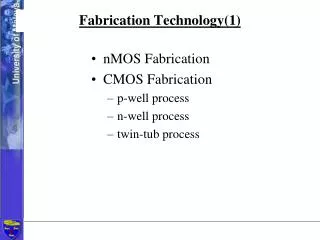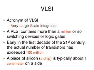
VLSI Fabrication Technology
200 likes | 467 Vues
VLSI Fabrication Technology. 1. Figure A.1 Silicon ingot and wafer slices. Figure A.2 (a) An 8-pin plastic dual-in-line IC package, (b) A 16-pin surface mount package. (e) n + diffusion (mask #4). (a) Define n -well diffusion (mask #1). (f) p + diffusion (mask #5).

VLSI Fabrication Technology
E N D
Presentation Transcript
Figure A.2 (a) An 8-pin plastic dual-in-line IC package, (b) A 16-pin surface mount package.
(e) n+ diffusion (mask #4) (a) Define n-well diffusion (mask #1) (f) p+ diffusion (mask #5) (b) Define active regions (mask #2) (g) Contact holes (mask #6) (c) LOCOS oxidation Figure A.3 A typical n-well CMOS process flow.
(h) Metallization (mask #7) (d) Polysilicon gate (mask #3) Figure A.3 (Continued)
Figure A.5 Cross sections of resistors of various types available from a typical n-well CMOS process.
Figure A.6 Interpoly and MOS capacitors in an n-well CMOS process.
Figure A.11 Cross-sectional diagram of a symmetrical self-aligned npn SiGe heterojunction bipolar transistor (HBT).
Figure A.13 Cross section along the plane AA¢ of a CMOS inverter.
Figure A.14 A set of photomasks for the n-well CMOS inverter. Note that each layer requires a separate plate: (a), (d), (e), and (f) dark-field masks; (b), (c), and (g) clear-field masks.