Download
1 / 8
120 likes | 534 Vues
This accessory enhances communication capabilities via Profibus-DP module for efficient data transmission and monitoring using RS-485 line. It features terminating resistance and a variety of communication speeds. The TRIO unit ensures temperature monitoring and remote functions for reliable operation. The product supports communication flexibility and reliability, meeting international standards for seamless integration. Use the included manual for detailed communication map and configuration instructions. Learn more about Profibus-DP on the Korean Profibus Association's website.

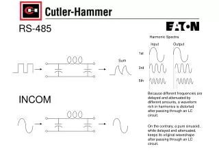
E N D
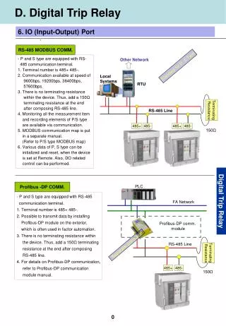
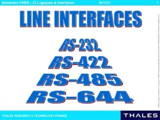
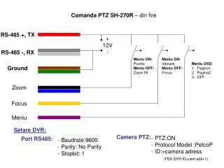
PLC FA Network Profibus-DP comm. module RS-485 Line Separate purchase Terminating Resistance 485+ 485- 150Ω D. Digital Trip Relay 6. IO (Input-Output) Port RS-485 MODBUS COMM. - P and S type are equipped with RS- 485 communication terminal. 1. Terminal number is 485+ 485-. 2. Communication available at speed of 9600bps, 19200bps, 38400bps, 57600bps. 3. There is no terminating resistance within the device. Thus, add a 150Ω terminating resistance at the end after composing RS-485 line. 4. Monitoring all the measurement item and recording elements of P/S type are available via communication. 5. MODBUS communication map is put in a separate manual. (Refer to P/S type MODBUS map) 6. Various data of P, S type can be initialized and reset, when the device is set at Remote. Also, DO related control can be performed. Other Network Standard for P, S Type Local Systems RTU Terminating Resistance RS-485 Line 485+ 485- 485+ 485- 150Ω Digital Trip Relay Profibus -DP COMM. - P and S type are equipped with RS-485 communication terminal. 1. Terminal number is 485+ 485-. 2. Possible to transmit data by installing Profibus-DP module on the exterior, which is often used in factor automation. 3. There is no terminating resistance within the device. Thus, add a 150Ω terminating resistance at the end after composing RS-485 line. 4. For details on Profibus-DP communication, refer to Profibus-DP communication module manual.
1 2 3 5 4 100 6 119 82.5 E. Digital Trip Relay Accessory 1. TRIO Unit ■ Function and Characteristics 1. Temperature and Remote I/O Unit (Below TRIO Unit) has remote closing, breaking, and temperature monitoring functions. 2. TRIO Unit aim for the open network selected by international communication protocol standard. 3. TRIO Unit can transfer information collected from ACB using RS-485/MODBUS and Profibus-DP communication. 4. TRIO Unit can detect ACB’s abnormal temperatures through its temperature monitoring function. 5. It establishes communication speed automatically according to master’s communication speed, thus maintain flexible communication relationships. - But, only when Profibus-DP was applied. - When MODBUS communication is being used, speed is decided upon its applied deep switch operation. 6. TRIO Unit obtain reliability by adding SBO (Select Before Operation). ■ External View and Composition ■ Switch Setting Digital Trip Relay Accessory 1 2 3 * Supports when MODBUS Communication is used. - Profibus-DP is automatically arranged according to master. ** Supports on both system(MODBUS and Profibus-DP).
E. Digital Trip Relay Accessory 1. TRIO Unit ■ Terminal Configuration 1 1 2 3 4 5 6 7 8 9 10 11 12 Digital Trip Relay Accessory ■ Terminal Configuration 2 1 2 3 4 5 6 7 8
1 2 3 4 5 6 7 8 E. Digital Trip Relay Accessory 1. TRIO Unit ■ Terminal Configuration 3 Female 2 7 3 8 4 * Connect only when using repeater. ■ LED Configuration Warning LED 1 LED 2 150 : : : : : : : : : Digital Trip Relay Accessory 20 10 LED 2 LED 1
Diagnosis for Circuit Break Diagnosis for Digital Input OCR Comm. Temperature sensor ADC MODBUS Profibus-DP for higher level Comm. Temperature sensor comm. E. Digital Trip Relay Accessory 1. TRIO Unit ■ Product Input Rating ■ Product Output Rating ■ Internal Configuration Digital Trip Relay Accessory
E. Digital Trip Relay Accessory 2. Profibus – DP Communication ■ Profibus – DP Communication Introduction Profibus is selected, applied, and produced independently by the manufacturer (Vender-independence). It is approved for vender’s independence and openness according to Profibus standard EN50170 which is a open field-bus standard that is extensively used in a process automation. Among them, DP is the most commonly used communication profile. It is applicable for Master-Slave communication between Master automation device which has a device level and decentralized slave I/O device to optimize the communication speed and price with the network which is suitable for FA service condition of Field Level. For more details on Profibus-DP, please refer to “Korean Profibus Association” Homepage. ( http://www.profibus.co.kr) ■ Communication Standard Digital Trip Relay Accessory Note. * Support through LSIS GM3/4/6 master modules.(G3L-PUEA/G3L-PUEB/G4L-PUEA/G4L-PUEB) * When using other manufacturers’ masters, use applicable parameter tool and configuration tool.
E. Digital Trip Relay Accessory 2. Profibus – DP Communication ■ Network Configuration • RS-485 transferring method : To connect profibus • load, bus configuration is displayed using bus • connector and bus terminal. • Simple and standardized loading and connecting • concept • Easy installation Electric network can be composed of bus or tree. Cable Connecting Terminal Block Terminating Terminal Setting Switch On: Terminating Terminal OFF: No Terminating Terminal Connecting Connector Electric Network Branch connection Terminating connection ■ Communication Cable Standard • Recommend Belden Network • Cables. • Type : Network Components • Protocol : DP • Certification : No • Cable Order No : 3077F • 3079A Digital Trip Relay Accessory ■ Data Exchange • Under TRIOU’s data exchange condition, it exchanges data periodically at pre-defined • communication speeds. • It handles new data by comparing with previous ones. • It is processed through using SBO function, when handling important commands such as breaker • CB or DO control. • TRIOU’s output data will be sent to master every 1.5 second about its applicable information from • trip relay without a master’s command.
When master sends request-frame to • slave, slave sends response-frame. E. Digital Trip Relay Accessory 3. MODBUS ■ Protocol Under RTU Mode, a data is processed on the bit-basis allowing to use only 8 bits when processing one data. More heavily condensed code will enable RTU Mode to handle large quantity of information comparing with other buses at the same transferring speed. ■ Physical Layer ■ Data Link Layer Digital Trip Relay Accessory ■ Communication Frame 3.5 Char. time [Char. Time] START Address 8bits Function 8bits Data END CRC 16bits [Address Range] [Function Range] [CRC Range] • Valid slave device address range : 0~247 decimal • TRIO Unit address range that is actually used : 1~247 decimal • In case the slave device address of frame where Master request to Slave is in the range of zero, it is the address where Master device is broadcasting to all Slaves. • When Master requests to Slave, transmit address field after filling it out with corresponding address. • It displays certain types of • function that should be dealt by slave. • TRIO Unit use 03, 04, 05, and 10 among its function codes. • In case of no error, Slave turns back the value sent from Master, otherwise it gives a response after setting MSB of the value sent from Master as 1. Use 2 bits CRC check procedures. Each of 8 bit data’s result (Address, Function, Data) is accumulated and CRC checked. Final data checked will be included in CRC field. EX) 0000 0001 ⇒ 0000 0001(normal) 1000 0001(error)