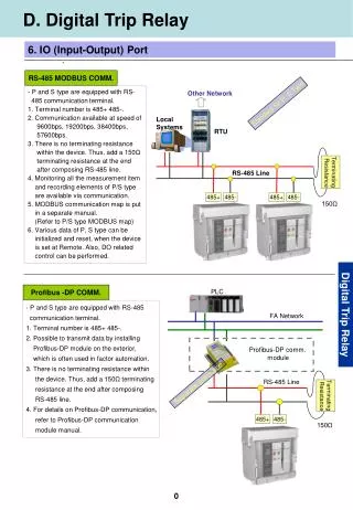
Modbus communication
Modbus communication. Host B. PSIN, ISDN, ADSL. @. PC network board. PSIN, ISDN, ADSL. Internet. Host B. gateways. PSIN, ISDN, ADSL. RS232 RS 485. @. PSIN, ISDN, ADSL. Internet. RS485 Modbus. ? =S= communication architecture. Ethernet. Port COM du PC. RS232. RS485 Modbus.


Modbus communication
E N D
Presentation Transcript
Host B PSIN, ISDN, ADSL @ PC network board PSIN, ISDN, ADSL Internet Host B gateways PSIN, ISDN, ADSL RS232 RS 485 @ PSIN, ISDN, ADSL Internet RS485 Modbus ? =S= communication architecture Ethernet Port COM du PC RS232 RS485 Modbus RS485 Modbus
Communication = exchange of several types of information Logical, digital information (O/C) for alarms and testing • circuit breaker status • alarms • protection unit status • earthing switch status Sepam Sepam Sepam SCADA Analog information • measurements • counters • remote readings and settings • disturbance readings for power monitoring/management
The measurements presented in a Sepam depend on the type of Sepam. Measurement readout phase currents, line to line voltages, frequency, real and reactive power, and power factor, accumulated real and reactive energy, peak demand phase current, peak demand real and reactive power, tripping currents, temperatures, thermal capacity used, number of starts and inhibit time, running hours counter. Readout of program logic resource status event counter values, logical input status, status of the remote annunciation bits (TS). Remote control writing of remote control orders (TC) Other functions time tagging, remote reading of Sepam settings (remote reading), remote setting of protections and control logic time delays (remote setting); transfer of disturbance recording data. Sepam data exchanged
PHYSICALLAYER 1 APPLICATIONLAYER 7 PRESENTATION LAYER 6 SESSIONLAYER 5 TRANSPORTLAYER 4 NETWORKLAYER 3 DATA LINKLAYER Bus concept: 2 Ethernet RS 485 & 232 - OSI: 7-layer architecture OSI = Open Systems Interconnection Example: Modbus • Data processing Network concept e.g. TCP/IP • End-to-end management Network interconnection • Data transmission
- topology between components Bus Point to point Meshed Ring Star
- type of transmission Simplex transmission: one-way Half duplex transmission: alternating two-way Full duplex transmission: simultaneous two-way
Start Stop 1 0 1 0 0 irregular transmission 1 character 1 0 1 1 0 0 0 1 1 0 Data - transmission mode Number of bits sent simultaneously • Parallel bus • Serial bus • Synchronous: clock = continuous transmission • Asynchronous:
Asynchronous transmission mode (cont'd) Need for a communication format • start = initializes the communication frame, indicates the start of the message. • useful data bits = useful data bits of the message. • error check = to check for transmission errors. • stop = indicates the end of the message. communication frame 0 1 start useful data bits error check stop
Twisted pair cable - medium • Distance: maximum length, line losses • Rate = cable capacity • Type of communication chosen: RS 485 or Ethernet • Environment (EMC, Temperature, etc.) • Price Simple to implement Low cost
RS232 RS485 PC devices PHYSICAL LAYER 1 Electrical levels 0 +5 +15V 1.5 + 5V 1 - 5 - 15V - 1.5 - 5V APPLICATIONLAYER 7 PC COM Port Max. rate 19200 Bauds 1Mbauds PRESENTATION LAYER 6 TRANSPORTLAYER 4 SESSIONLAYER Multipoint bus Half duplex Link 5 Point to Point Asynchronous RS 485 Modbus NETWORK LAYER 3 Length 30 m 1200 m DATA LINKLAYER 2 Control lines RTS/CTS No (flows) - physical layer standards: RS232 and RS485
Communication Settings • Sepam address • Speed • Parity
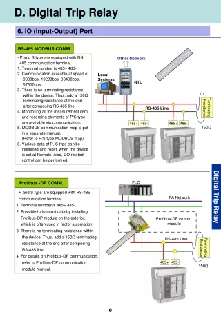
Sepam series 20 40 80 communication Interfaces Module ACE 949-2 Sepam connection to a Modbus 2 wires network Module ACE 959 Sepam connection to a Modbus 4 wires network Module ACE 937 Sepam connection to a Modbus optical fiber network
ACE 969 interface Sepam series 20 40 80double port plus DNP3 and IEC 870 5 103protocol
Architecture of the RS485 network • Pear to pear • bus
Optical network architecture • pear to pear • star • daisy chain
Modbus protocol master master Characterization of exchanges Modbus protocol may be used to read or write one or more bits, one or more words, the content of the event counter or the contents of the diagnosis counters. functions available: • reading of n output or internal bits, • reading of n input bits, • reading of n output or internal words, request broadcasting reply slave slave slave slave slave slave • reading of n input words, • writing of 1 bit, • writing of 1 word, • fast reading of 8 bits, • diagnosis of exchanges, • reading of event counter, • writing of n bits, • writing of n words.
PHYSICAL LAYER 1 APPLICATIONLAYER 7 PRESENTATION LAYER 6 TRANSPORTLAYER 4 SESSIONLAYER 5 NETWORK LAYER 3 DATA LINKLAYER 2 - for PLC communication • For RS 485 or RS 232, and other links… • Created in 1979 by Modicon • Half-duplex protocol: one "speaker" at a time • Master-slaves • query / reply • broadcasting with no feedback Maximum number of slaves: 31
: Address Function Data LRC Check CR LF 0D Hex 0A Hex 3A Hex silence Address Function Data CRC Check silence Silence >= 3.5 characters - structure of a Modbus frame • ASCII (American Standard Code of Information Interchange) Modbus Tolerance of one second silence between characters • RTU (Remote Terminal Unit) Modbus Used more since faster
functioncode 0 to FFh data CRC 16 1 byte 1 byte N bytes 2 bytes Presentation of request and reply frames when the message is received by the slave, the slave reads the check word and accepts or refuses the message data required for the request, bit or word addresses, bit or word values, number of bits or words The code is used to select the available requests Request question reply Tr < 10 ms The time is given with the following parameters: • 9600 bauds, • 8-bit format, odd parity, 1 stop bit. addresses of bits or words read, value of bits or words read, number of bits or words Reply functioncode data 0 to FFh CRC 16 1 byte 1 byte N bytes 2 bytes
broadcasting exchange i Modbus protocol: transmission medium occupancy diagram analyse and next exchange wait wait wait master request request to slave 1 to slave N slave 1 answer Analyse and answer slave N answer simultaneous execution of the order by all the slaves physical medium time exchange i - 1 exchange i + 1
Diagnosis counters Sepam manages the following diagnosis counters: • CPT1, first word: number of correct frames received, whether or not the slave is concerned, • CPT2, second word: number of frames received with CRC errors, or frames received that are greater than 255 bytes and not interpreted, or frames received with at least one character that has a parity error, “overrun”, “framing”, “break” on the line. An incorrect rate causes incrementation of CPT2, • CPT3, third word: number of exception replies generated (even if not sent, as result of a broadcast request), • CPT4, fourth word: number of frames specifically addressed to the station (excluding broadcasting), • CPT5, fifth word: number of broadcast frames received with no errors, • CPT6, sixth word: not significant, • CPT7, seventh word: number of “Sepam 2000 not ready” replies generated, • CPT8, eighth word: number of frames received with at least one character that has a parity error, “overrun”, “framing”, “break” on the line, • CPT9, ninth word: number of correct requests received and correctly executed. The counters may be accessed via the dedicated reading function (see Modbus protocol function 11 in appendix).
Time-sequencing A date is associated to each event: • change of status of logic inputs • change of status of automation data TS • Internal data necessary for time-sequencing, time-setting, synchronization… Internal clock in Sepam: year, month, day, hour, minute and milliseconds (0 to 59999).
Time-sequencing, synchronization Scada scada Input I21, 10 to 60 s synchronization signal. clock Sepam Sepam time-setting 4 words Modbusnetwork Modbusnetwork Synchronization link Sepam Sepam “Internal synchronization via the comunication network” architecture “External synchronization” via a logic input architecture 10 s 20 s 30 s message ∆ = ± 4 s
Exchange Principle Storage zone 64 events Status Change Master Request Zone 1-Request Reply Zone 3-Acknowledgement 4 events 2-Reading
40 Exchange word Master 1 Reading 4 event zone Acknowledgment 80 Exchange word Master 2 Reading 4 event zone Acknowledgment Exchange principle Inside Sepam 64 eventzone Inside Sepam 64 eventzone
exchangenumber number of events type of channel: 0 for input/800 for others modbus data address reserved: Ø data status 0/1 not used year month day hour minutes milliseconds 0 to 59999 Time-sequencingExchange table 1/reading if ≠ 0 in the event table2/writing to 0 for the following exchange incrementedupon each exchange 0 = empty tablex = x events4 maximum pollingword event 1 event 2 event 3 event 4 8 mots Max. stock: 64 events.
Remote reading and remote setting • Protection and parameter settings available • Setting of protection functions • Sepam general characteristics
Reading of the settingsExchange principle Protection setting zone Master 50/51 overccurrent 50N/51N eath fault 27 under volltage Request Zone 1-Request Reply Zone 2-Reading
B15 B14 B13 B12 B11 B10 B09 B08 B07 B06 B05 B04 B03 B02 B01 B00 function code unit number B15 B14 B13 B12 B11 B10 B09 B08 B07 B06 B05 B04 B03 B02 B01 B00 function code unit number settings ………… (specific fields for each function) ………… Remote parameter reading function Request frame The request is made by the supervisor, by means of a modbus "write words" command (code 6 or 16) at the address D080h of a 1-word frame which consists of the following: D080h Reply frame The reply sent back by Sepam is contained in a zone with a maximum length of 125 words at the address D000h, which consists of the following: D00h
Remote settingsExchangePrinciple Protection setting zone Writing zone Master 50/51 overccurrent 50N/51N eath fault 27 under volltage 1-Writing request Reply zone 2- reading request 3-check
B15 B14 B13 B12 B11 B10 B09 B08 B07 B06 B05 B04 B03 B02 B01 B00 function code = 01 unit number = 01 type of curve = 00 00 (most significant) type of curve = 00 00 (constant itme) set point = 00 00 (most significant) set point = 00 64 (set point at 100 A) time delay = 00 00 (most significant) time delay = 00 0A (time delay set to 10 x 10 = 100 ms) 00 00 (most significant) 00 00 (following values not significant, initalized to 0) Remote reading of settings Data format All the settings are transmitted in the form of signed 32-bit integers (encoded, as a complement of 2). Particular setting values A value equal to 7FFF FFFFh means that the setting is out of its validity range. To inhibit a protection function, simply set the inhibition parameter to 8000 0000h, the other parameters stay the same. If all the setting values are read as 8000 0000h, it means that the protection function concerned is inhibited.
Disturbance recording Presentation Disturbance recording is used to store analog and logical values. Sepam records a maximum of two disturbance records. Each record contains two files: configuration file with suffix .CFG, data file with suffix .DAT. The files are read by the supervision system via the Jbus link. A record may be transferred until it is overwritten by a new record.