
Wireless Sensor Networks for Complex Data Processing
Explore the advantages of Sutron's SDI/MODBUS Wireless Sensor Networks including scalability, reliability, and cost-effectiveness. Learn about the technical specifications and installation configurations. Competitive analysis with Banner Engineering ModbusLink Plus provided.

Wireless Sensor Networks for Complex Data Processing
E N D
Presentation Transcript
Advantages Sutron's SDI/MODBUS Wireless Sensor Networks • Sites where wiring is not practical (across a river, on rotating spindle etc). • Avoids expensive wiring, conduits, installation and maintenance. • Makes system easily scalable (add more sensors) • Less susceptible to vandalism. • Highly reliable, scalable, secure, robust, cost effective • Multiple sensor types • Complex data processing/analysis available w/9210 Master
Key Technical Specifications • Operating Frequency: 2.4 Ghz • Network type: Ad-hoc homogenous mesh • Range: 1mile per hop • Latency: 1s per hop • Power Consumption: 450 µA @ 3.6v (average) • Internal Battery: 19Ah Lithium D-cell • External Power: 8-16v dc • Operating Temp: -40C to +60C • Enclosure: NEMA rated (4.72”x 3.15” x 2.17”) • Protocol : Modbus RTU • Interfaces: RS-232, RS-485 • Status indicators: 3 LED (red/green/orange)
Sensor Inputs • 3 independently switched 12v supplies • Programmable warmup for each supply • 24 bit ADC • Built in 2.5v precision reference • 2 x Single ended analog inputs (0-5v) • 3 x Differential Inputs • 2 x SDI Sensors • 1 x Frequency input • 1 x Digital Input (Rain Gauge)
Compatible Equipment • ModbusLink-M • 9210 Data Logger via available RS232 or RS485 port • 8310 Data Logger via available RS232 or RS485 port (version TBD) • PLC or PC with serial port • ModbusLink-S • Sutron Radar Level Sensor – RLR-0003-1 • Constant Flow Bubbler – 56-0133-25, 56-0134 • Stage Discharge Recorder (SDR) - SDR-0001-1 • Submersible Pressure Sensor INW-PT12 • Any Modbus Sensor with RS232 or RS485, up to 57600 baud.
Installation Configurations Simple Installation with 1 Master & 1 Slave
ModbusLink – Network Features • All nodes are capable of routing messages while remaining in low power mode • Multiple ModbusLink networks can co-exist without interference. • Ad-Hoc mesh network (Automatic route formation) • Most efficient route to destination will be used • Routes periodically refreshed to improve reliability • Dynamic route tables, no RF/memory overhead for maintaining unnecessary routes. • Robust - New routes discovered if intermediate routes fail • Simple Network commands to maintain/query Network status(Network Scan, Blink Remote LEDsetc) • Simple command line interface to configure network / Modbus parameters
Network basics 3 4 G 2 6 5 Logger
Network basics • 3 types of Network Route messages • Route Request (RREQ) • Route Response (RREP) • Route Error (RERR)
Network basics 3 4 G 2 6 5 • Example Gateway -> 6 • G broadcast RREQ for addr 6 • 2,3,5 receive RREQ from G • 2,3,5 update route table (2->G …) • 2,3,5 rebroadcast RREQ • 4 receives RREQ from 2 & 3 • 4 Discards 2nd RREQ as hop cnt not less • 4 rebroadcasts RREQ
Network basics 3 4 G 2 6 5 • 6 receives RREQ from 2 • Forward Route complete (Unicast) • Update Table (6->2----->G) • RREP to 2 (dest G) • 2 receives RREP, updates Table (2->6) • 2 fwds RREP to G Logger
Network basics 3 4 M 2 6 5 Message Delivery • Route Formation Complete • Route Table (G) => 6,2,Sq#,HopCnt • Route Table(2) => 6,6,Sq#,HopCnt => G,G,Sq#, HpCnt • Route Table (6) => G,2,Sq#,HopCnt • Min RSSI threshold for reliability • Route’s refreshed every 48hrs
Competitive Analysis Compare Sutron with Banner Engineering
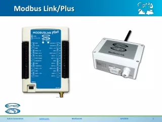
ModbusLinkPlus • 3 independently programmable switched 12v power supplies for sensors. • 2 X Single ended analog • 2.5v reference voltage for bridge sensors • 3 x Differential inputs • 1 SDI-12 Sensor • 2x Digital inputs (frequency, counter)
Ordering Part # Description MBLINKPLUS-1 Wireless network node with I/O (transceiver with built-in SDI-12, Analog & Digital Inputs). No Enclosure MBLINKPLUS-1E Wireless network node with I/O (transceiver with built-in SDI-12, Analog & Digital Inputs) With NEMA Enclosure & internal battery 6661-1325-1 External antenna Kit(3dBi antenna, 20’ low loss cable, mounting kit)
Future Support • Wireless Radar • Wireless Tipping bucket
System Configuration • 1 x ModbusLink – Master • Sutron 9210 Datalogger • 8 x ModbusLink - Slaves • 8 x INW Pressure sensors (Water Level + temperature)
Master Station ModbusLink Master