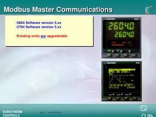
Modbus Embedded Controller
Modbus Embedded Controller. Kevin Ho. May,27,2004. What is Modbus ?. An open data communication protocol Published by Modicon http://www.modicon.com Open structure Flexible Widely known Supplied by many SCADA and HMI software 2 serial transmission modes: ASCII 10 bits


Modbus Embedded Controller
E N D
Presentation Transcript
Modbus Embedded Controller Kevin Ho May,27,2004 P.1
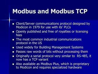
What is Modbus ? • An open data communication protocol • Published by Modicon • http://www.modicon.com • Open structure • Flexible • Widely known • Supplied by many SCADA and HMI software • 2 serial transmission modes: • ASCII 10 bits • RTU (Binary) 11 bits • Communication interface • RS-232/485 • Ethernet (TCP/IP) • Modbus Organization (http://www.modbus.org/default.htm) P.2
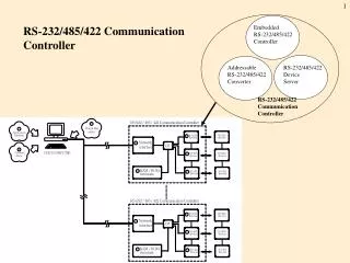
Application Structure (general) Modbus Client (Master) SCADA HMI Internet RS-232/485 Modbus Device (Slave) Modbus Device (Slave) P.3
Query-Response Cycle Query Station Number Function Code Station Number Data Bytes (Flexible) Function Code Data Bytes (Flexible) Error Check Error Check Response P.4
Hardware Classification • Station Device: 0 ~ 255 • Digital input module • 1xxxx: 4 digits for hexadecimal address (0000 ~ FFFF) • 1xxxxx: 5 digital for decimal address (0 ~ 65535) • Digital output module • 0xxxx: 4 digits for hexadecimal address (0000 ~ FFFF) • 0xxxxx: 5 digital for decimal address (0 ~ 65535) • Analog input module • 3xxxx: 4 digits for hexadecimal address (0000 ~ FFFF) • 3xxxxx: 5 digital for decimal address (0 ~ 65535) • Analog output module • 4xxxx: 4 digits for hexadecimal address (0000 ~ FFFF) • 4xxxxx: 5 digital for decimal address (0 ~ 65535) • Begining of Address • From 0: VLC • From 1: InduSoft, iFix P.5
Two Serial Transmission Modes • ASCII Mode • Data system ASCII character, ‘0’~’9’,’A’~’F’ • Bits per data unit • Error Check Field Longitudinal Redundancy Check (LRC) • RTU Mode • Data system 8-bit Binary, 00~FF • Bits per data unit • Error Check Field Cyclical Redundancy Check (CRC) 1 Start Bit 7 Data Bits 1 Parity Bit (Even/Odd) 1 Stop Bit 1 Start Bit 7 Data Bits 2 Stop Bit 1 Start Bit 8 Data Bits 1 Parity Bit (Even/Odd) 1 Stop Bit 1 Start Bit 8 Data Bits 2 Stop Bit P.6
Modbus Message Packet • ASCII Mode • RTU Mode • Modbus Plus network Byte 0, 1: transaction ID – usually 0 Byte 2, 3: protocol ID = 0 Byte 4, 5: number of bytes following Start Station Number Function Code Data Error Check End 1 Char 2 Chars 2 Chars n Chars 2 Chars 2 Chars : LRC CR,LF Start Station Number Function Code Data Error Check End 3.5 Char 1 Char 1 Char n Chars 2 Chars 3.5 Chars Silence CRC Silence Prefixed Data Station Number Function Code Data 6 x 8 Bits P.7
Modbus Function Code • 01: read DOs (0xxxx) • 02: read DIs (1xxxx) • 03: read AOs (4xxxx) • 04: read AIs (3xxxx) • 05: write single DO (0xxxx) • 06: write single AO (4xxxx) • 15: wirte DOs (0xxxx) • 16: write AOs (4xxxx) P.8
8000-MTCP System Application Multi Serial Clients (Masters) Multi Modbus/TCP Clients (Masters) command protocol depend on serial devices Internet Modbus/TCP command protocol VxComm Technique Modbus/TCP Slave RS-485 RS-232 P.9
8000-MTCP System Application Multi Modbus/TCP Clients (Masters) Modbus/TCP Internet Modbus/RTU Modbus/RTU P.10
8000E –MTCP Features • Supports Modbus/TCP communication protocol to access I/Os that plug on slots • Supports VxComm technique for every COM port of controllers • Auto scan I/O modules • Automatically range register address of I/O modules • Allows multi-client (or master) access simultaneously • Online configuration (using Modbus Utility via Ethernet) • Supports I-8000 and I-87000 series I/O modules • Firmware updateable and programmable P.11
Tools • MiniOS7 Utility (Download files and update OS image) • PCDiag (Diagnostic tools) • NAP OPC Server (Check I/O action quickly) • MBTCP.exe (Check Modbus/TCP package details) • MBRTU.exe (Check Modbus/RTU package details) P.12
8000E-MTCP Program Block Modbus Client (Master) Modbus protocol User-defined protocol SCADA HMI Modbus Embedded Controller Check Modbus Request Update I/O RS-485 Run User Process . . . I-7000 I-7000 I-87K RS-232 PLC P.13
8000E -MTCP SDK Features • 2 communication protocols • User-defined: port 10000 • Modbus/TCP: port 502 • 4 Internal register tables (MTDemo50) iMemory_DI iMemory_DO iMemory_AI iMemory_AO • Access I/Os that plug on slots (MTDemo51) • Link I-7000 or I-87000 series modules via COM ports (MTDemo52) • Modbus/RTU master (MTDemo53) Points of DI module plug on slots User-defined Points of DO module plug on slots User-defined Points of AI module plug on slots User-defined Points of AO module plug on slots User-defined P.14
User-defined Internal Registers Modbus/TCP Write Modbus Kernel Read Slot iMemory_DI iMemory_DO User Process RS-232 iMemory_AI iMemory_AO RS-485 . . . I-7000 I-7000 I-87K P.16
Be a Modbus/RTU Master iMemory_DI iMemory_DO User Process Modbus/RTU iMemory_AI iMemory_AO Modbus/RTU User-defined Input Input User-defined Output Output int ModbusMaster2Slave(int iPort,unsigned char cNetID, unsigned char cFunction, intiControllerMemoryBaseAddress, int iDeviceMemoryBaseAddress,int iIOCount); P.17
Modify 8000E-MTCP Firmware • User.c void UserInit(void) { int iRet; iRet=InitModbus(); } void UserLoopFun(void) { UpdateIOModule(); CheckModbusRequest(iModbusUpLinkPort); //Is any Modbus/RTU request from COM port ? CheckLEDMenu(); } int UserCmd(unsigned char *Cmd,unsigned char *Response) { int iRet; if(Cmd[0]=='!') iRet=Configuration(Cmd,Response); return 1; } P.18
Modify 8000E-MTCP Firmware • MBTCP_8E.h //Memory base address of every slot extern unsigned int iMemoryAddr_DI[8]; extern unsigned int iMemoryAddr_DO[8]; extern unsigned int iMemoryAddr_AI[8]; extern unsigned int iMemoryAddr_AO[8]; //I/O points of every slot extern unsigned int iMemoryNum_DI[8]; extern unsigned int iMemoryNum_DO[8]; extern unsigned int iMemoryNum_AI[8]; extern unsigned int iMemoryNum_AO[8]; //The I/O values extern unsigned char* iMemory_DI; extern unsigned char* iMemory_DO; extern int* iMemory_AI; extern int* iMemory_AO; //Total DI,DO,AI,AO points extern int iDINum,iDONum,iAINum,iAONum; P.19
7188E-MTCP System Application Multi Serial Master (Clients) Multi Modbus/TCP Masters (Clients) Modbus/TCP command protocol Single Modbus/RTU Masters (Clients) command protocol depend on serial devices Internet Modbus/RTU command protocol VxComm Technique RS-232/485 Modbus/RTU RS-485 RS-232 P.20
7188E-MTCP COM Port Enable Mode • VxComm (Virtaul COM) • Modbus/RTU Links to Modbus/RTU slave devices • Programming Links to RS-232/485/422 devices (controlled by user’s program) • UpLink Links to a Modbus/RTU master device • Debug Prints out communication messages P.21
7188E-MTCP Internal Block Modbus Client (Master) Modbus protocol User-defined protocol SCADA HMI Modbus Embedded Controller Expansion Bus X board Check Modbus Request RS-485 Read/Write I/O … Run User Process I-7000 I-7000 I-87K RS-232 Modbus/RTU P.22
7188E-MTCP Features • Converts single Modbus/TCP to multi Modbus/RTU (Modbus/TCP slave port) • Converts single Modbus/RTU to multi Modbus/RTU (Modbus/RTU slave port) • Supports VxComm technique for every COM port of controllers • Allowed multi-client (or master) access simultaneously • Firmware updateable and programmable P.23
7188E-MTCP SDK Features • Modbus/TCP to Modbus/RTU converter (Default function) • 4 Internal register tables (MTDemo00) iMemory_DI iMemory_DO iMemory_AI iMemory_AO • Link I-7000 or I-87000 series modules via COM ports (MTDemo01) • Access X-board (MTDemo02) • Modbus/RTU master (MTDemo03) User-defined User-defined User-defined User-defined P.24
User-defined Internal Register (7188XB,7188E) Modbus/TCP Write Modbus Kernel Read Expansion Bus X board iMemory_DI iMemory_DO User Process RS-232 iMemory_AI iMemory_AO RS-485 . . . I-7000 I-7000 I-87K P.25
Modbus/RTU master (7188XB,7188E) iMemory_DI iMemory_DO User Process Modbus/RTU iMemory_AI iMemory_AO Modbus/RTU User-defined Input Input User-defined Output Output int ModbusMaster2Slave(int iPort,unsigned char cNetID, unsigned char cFunction, intiControllerMemoryBaseAddress, int iDeviceMemoryBaseAddress,int iIOCount); P.26
Modbus Gateway Application 1 • Original system: one PC connect to a HoneyWell PLC • Requirement: allow two extra PCs to connect to the same PLC • Problem: the communication interface of the PLC is RS-232. RS-232 is point to point interface, it cannot links 4 devices (3 PCs + 1 PLC) HoneyWellModbus/RTU device iFix (A) RS-232 @ 38400 bps iFix (B) iFix (C) P.27
Thinking 1 (RS-485 method) • Thinking: RS-485 is a broadcast interface. Change to RS-485 interface can allow all PCs communicate with the PLC. • Problem: The PLC will broadcast its response to every PC. The two PCs will feel confuse. • Final: Doesn’t work iFix (A) 2 Response iFix (B) 2 1 Request iFix (C) 2 P.28
Thinking 2 (Ethernet to RS-232 converter) • Thinking: the converter allow the 3 PCs share one COM port • Problem: The communication band width is shared by the 3 PCs. Thus the communication efficiency becomes 1/3. • Final: Works but not efficient. iFix (A) Ethernet/RS-232 converter 4 COM1 @ 38400 bps HoneyWellModbus/RTU device Modbus/RTUResponse 1 11 7 3 iFix (A) Modbus/RTUResponse 2 8 6 10 5 Modbus/RTU Request Modbus/RTU Request iFix (A) 12 9 P.29
Thinking 3 (Modbus/TCP Gateway) • Thinking: Doesn’t need to install extra VxComm driver on the PC • Problem: The communication band width is shared by the 3 PCs. Thus the communication efficiency becomes 1/3. • Final: Works but inefficient. iFix (A) 7188E-MTCP 4 COM1 @ 38400 bps HoneyWellModbus/RTU device Modbus/RTUResponse 1 11 7 3 iFix (B) Modbus/TCPResponse 2 8 6 10 5 Modbus/TCP Request Modbus/RTU Request iFix (C) 12 9 P.30
Thinking 3 (Modbus/TCP Gateway) • Thinking: 7188E polls PLC’s memory to its share memory The 3 PCs get PLC’s data from the share memory • Goods: Ethernet communication is much faster than RS-232, The 3 PCs can get PLC data in very short time (less than 1 second) • Final: Works and efficient iFix (A) 7188E-MTCP 2 HoneyWellModbus/RTU device Modbus/RTUResponse 1 COM1 @ 38400 bps ShareMemory B iFix (B) Modbus/TCPResponse A 4 3 Modbus/TCP Request Modbus/RTU Request iFix (C) 6 5 P.31
Modbus Gateway Application 2 • Original system: one ABB DCS connect to one AB PLC • Requirement: The system needs to include two AB PLC more. • Problem: The communication interface of the DCS and PLC is RS-232 AB PLC #1 RS-232 @ 9600 bps AB PLC #2 AB PLC #3 P.32
Solution • Hardware: 7188XB + X505 = 4* RS-232 port + 1* RS-485 • Software: 7188XB polls 3 AB PLC’s data to its share memory ABB DCS access the 7188XB to get all data of the 3 AB PLCs 7188XB ABB DCS AB PLC #1 ShareMemory RS-232 @ 9600 bps Analog Output AB PLC #2 Analog Input DI DO AI AO AB PLC #3 Analog Input P.33
Multi PC access PLCs on the same RS-485 Polling PLCs backgroundly 7188E-MTCP 2 Modbus/RTUResponse 1 ShareMemory RS-485 B Modbus/TCPResponse A 4 Modbus/RTU Request 3 Modbus/TCP Request PLC#1 PLC#2 PLC#3 6 5 P.34