Understanding Adders and ALUs in Computer Architecture
Dive into the crucial components of computer architecture, focusing on adders and arithmetic logic units (ALUs). This guide covers binary half-adders and full-adders, explaining their implementations, including the use of multiplexers and gate networks. Learn about ripple-carry adders, their latency, and speed-up methods like carry-skip. We also explore counting, incrementation circuits, and the role of logic and shift operations in ALUs. This comprehensive overview will enhance your understanding of fundamental computing machinery.

Understanding Adders and ALUs in Computer Architecture
E N D
Presentation Transcript
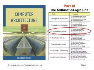
Part IIIThe Arithmetic/Logic Unit Computer Architecture, The Arithmetic/Logic Unit
III The Arithmetic/Logic Unit Computer Architecture, The Arithmetic/Logic Unit
10 Adders and Simple ALUs Computer Architecture, The Arithmetic/Logic Unit
10.1 Simple Adders Figures 10.1/10.2 Binary half-adder (HA) and full-adder (FA). Computer Architecture, The Arithmetic/Logic Unit
Full-Adder Implementations Figure10.3 Full adder implemented with two half-adders, by means of two 4-input multiplexers, and as two-level gate network. Computer Architecture, The Arithmetic/Logic Unit
Critical path Ripple-Carry Adder: Slow But Simple Figure 10.4 Ripple-carry binary adder with 32-bit inputs and output. Computer Architecture, The Arithmetic/Logic Unit
10.2 Carry Propagation Networks gi = xiyi pi = xiyi Figure 10.5 The main part of an adder is the carry network. The rest is just a set of gates to produce the g and p signals and the sum bits. Computer Architecture, The Arithmetic/Logic Unit
Ripple-Carry Adder Revisited The carry recurrence: ci+1 = gipici Latency of k-bit adder is roughly 2k gate delays: 1 gate delay for production of p and g signals, plus 2(k – 1) gate delays for carry propagation, plus 1 XOR gate delay for generation of the sum bits Figure 10.6 The carry propagation network of a ripple-carry adder. Computer Architecture, The Arithmetic/Logic Unit
First Carry Speed-Up Method: Carry Skip Figures 10.7/10.8 A 4-bit section of a ripple-carry network with skip paths and the driving analogy. Computer Architecture, The Arithmetic/Logic Unit
10.3 Counting and Incrementation Figure 10.9 Schematic diagram of an initializable synchronous counter. Computer Architecture, The Arithmetic/Logic Unit
Circuit for Incrementation by 1 Substantially simpler than an adder Figure 10.10 Carry propagation network and sum logic for an incrementer. Computer Architecture, The Arithmetic/Logic Unit
10.5 Logic and Shift Operations Conceptually, shifts can be implemented by multiplexing Figure 10.15 Multiplexer-based logical shifting unit. Computer Architecture, The Arithmetic/Logic Unit
Arithmetic Shifts Purpose: Multiplication and division by powers of 2 sra $t0,$s1,2 #$t0($s1) right-shifted by 2 srav $t0,$s1,$s0 #$t0($s1) right-shifted by ($s0) Figure 10.16 The two arithmetic shift instructions of MiniMIPS. Computer Architecture, The Arithmetic/Logic Unit
Practical Shifting in Multiple Stages Figure 10.17 Multistage shifting in a barrel shifter. Computer Architecture, The Arithmetic/Logic Unit
Logic unit 0 Arith unit 1 10.6 Multifunction ALUs Logic fn (AND, OR, . . .) Operand 1 Result Operand 2 Select fn type (logic or arith) Arith fn (add, sub, . . .) General structure of a simple arithmetic/logic unit. Computer Architecture, The Arithmetic/Logic Unit
An ALU for MiniMIPS Figure 10.19 A multifunction ALU with 8 control signals (2 for function class, 1 arithmetic, 3 shift, 2 logic) specifying the operation. Computer Architecture, The Arithmetic/Logic Unit