Week 1 & 2 Computer Organization & Architecture
Week 1 & 2 Computer Organization & Architecture. Introduction to Basic Computer Organization with its peripherals. computer architecture & its functioning. General overview of programming languages & its compilations. Introduction to basic computer organizations and Architecture.


Week 1 & 2 Computer Organization & Architecture
E N D
Presentation Transcript
Week 1 & 2 Computer Organization & Architecture Introduction to Basic Computer Organization with its peripherals. computer architecture & its functioning. General overview of programming languages & its compilations.
Introduction to basic computer organizations and Architecture • Definition of computer & its block diagram • Von man Neumann machine • Functioning of computers • Bus Structure • Computer Organization • Computer Architetcure
Computer • Computer : Computer is an electronic machine which accepts the input from input device , transfers, do operation on data and gives the out put. • Peripherals or parts of computers • Input device : Accepts the data/program . Ex. Keyboard, mouse and so on. • Output Device: Used to give the result. • Ex. Monitor, printer and so on. • Central processing unit(C.P.U.) : Further divided into • Arithmetic logic unit(A.L.U) • Memory unit(M.U) • Control Unit(C.U)
Block diagram of computer Arithmetic and Input logic Memory Output Control I/O Processor Figure 1.1. Basic functional units of a computer.
Memory unit( M.U): Used to store the data in binary form from the input device and gives to the output to the output device. • Two classes of memory • Primary storage • Fast • Programs must be stored in memory while they are being executed • Address • RAM and memory access time • Memory hierarchy – cache, main memory • Secondary storage – larger and cheaper
Arithmetic Logic Unit(A.L.U.): used to fetch the data from the memory process it and aging send the data to the memory. • Performs the Arithmetic and logic operations • Control Unit • All computer operations are controlled by the control unit. • The timing signals that govern the I/O transfers are also generated by the control unit
There are many ways to connect different parts inside a computer together. • A group of lines that serves as a connecting path for several devices is called a bus. • Address/data/control
Von Neumann Architecture • Von Neumann Architecture consists of mainly 5 parts. • Input • Output device • Central Processing unit (C.P.U.) • Arithmetic Logic Unit (A.L.U). • Control Unit (C.U.) • Memory Unit (M.U)
Out Put Device : It is used to display the result eg: Monitor, printer and so on. • Input Device : It is used to enter the data .Eg. Keyboard, mouse and so on. • Central Processing Unit : (C.P.U.) • Memory Unit (M.U.) : It is used to store the data in the form of binary bits. • Data from the keyboard transfers to memory. • Memory of 2 types • Primary Memory: Used to store the data temporarily.eg. Main memory ,RAM, SRAM, DRAM. • Secondary memory : Used to store the data permanently. eg. Magnetic disks, magnetic bubbles and drums.
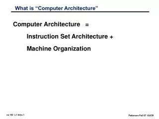
Computer Architecture • Refers to specification of the relationship between different hardware components of a computer system. • It defines high and low level of abstractions. • At high level CPU is presented and low level its parts like ALU,MU,CU represented
Computer Organization • Organization is how features are implemented • Control signals, interfaces, memory technology. • e.g. Is there a hardware multiply unit or is it done by repeated addition? Computer organization is a study of a Computer Architecture. E.g. Memory, Registers, RAM, ROM, CPU, ALU, 16 bit/ 32 bit/ 64 bit architecture, what different parts makes a computer, etc.
Programming Languages. • There are 4 types of programming languages. • High Level Language • Middle Level Language • Low level Language • Assembly Level Language.
Compiler : It is used to translate the Highlevel language (English statements) to low level language (1 ‘ 0’s).Compile entire program one at time. eg. Pascal, Basic, Fortran and so on. • Interpreter : Used to translate the program high level language into low level language. It translates instruction by instruction.eg. Java
Assembler : Used to translate the Assembly level language (Mnemonics) into low level language. • Microprocessor: This is a smallest part of the processor which performs the following functions like • Storing data • Transferring • Performing Arehtmetic and logical operations. • Shift Operations and so on. • Eg: 8086,80386.
Week 3 Organization of the IBM Personal computers • Architecture • Registers • Memories • Addressing modes • Instruction sets • Interrupts
Organization of the 8088/8086 CAP/IT221
Organization of the 8088/8086 2 main components: . Execution Unit (EU). . Bus Interface Unit (BIU). EU: ALU + Registers (AX, BX, CX, DX, SI, DI, BP, and SP) + FLAGS register. ALU: performs arithmetic & logic operations. Registers: store data FLAGS register: Individual bits reflect the result of a computation. CAP/IT221
Organization of the 8088/8086 BIU: facilitates communication between the EU & the memory or I/O circuits. Responsible for transmitting addresses, data, and control signals on the buses. Registers (CS, DS, ES, SS, and IP) hold addresses of memory locations. IP (instruction pointer) contain the address of the next instruction to be executed by the EU. CAP/IT221
Organization of the 8088/8086 16-bit registers, 1M Bytes Memory Registers: Information is stored in registers Registers are classified according to the functions they perform CAP/IT221
Registers • Data registers: 4 general data registers hold data for an operation. • Address registers: (segment, pointer and index registers) hold the address of an instruction or data. • Status register: FLAG register keeps the current states of the processor. • 14 16-bit registers CAP/IT221
Register CAP/IT221
General Data Register: Used for general data manipulation. • They are 16-bit registers that can also be used as two 8 bit registers: low and high bytes can be accessed separately → more registers to use when dealing with byte-size data. • In addition to being general-purpose registers, they perform special functions CAP/IT221
AX (Accumulator) • Most efficient register for arithmetic, logic operations and data transfer: the use of AX generates the shortest machine code. • In multiplication and division operations, one of the numbers involved must be in Al or AX BX (Base) Can hold addresses (offset) CAP/IT221
CX (Counter) Counter for looping operations: loop counter, in REP instruction, and in the shift and rotate bits DX (Data): Used in multiply and divide, also used in I/O operations CAP/IT221
Pointer Registers • SP (Stack Pointer): Used with SS for accessing the stack segment. • BP ( Base Pointer): Used with SS to access data on the stack. However, unlike SP, BP can be used to access data in other segments. CAP/IT221
Instructionpointer IP (Instruction pointer):Points to the next instruction. Used with CS.
Flags register Flags:Bits specify status of CPU and information about the results of the arithmetic operations. CAP/IT221
Registers of x86 • Carry Flag (CF) - this flag is set to 1 when there is an unsigned overflow . • Parity Flag (PF) - this flag is set to 1 when there is even number of one bits in result, and to 0 when there is odd number of one bits . • Auxiliary Flag (AF) - set to 1 when there is an unsigned overflow for low nibble (4 bits). • Zero Flag (ZF) - set to 1 when result is zero. For non-zero result this flag is set to 0.
Registers of x86 • Sign Flag (SF) - set to 1 when result is negative. When result is positive it is set to 0. (This flag takes the value of the most significant bit.) . • Trap Flag (TF) - Used for on-chip debugging . • Interrupt enable Flag (IF) - when this flag is set to 1 CPU reacts to interrupts from external devices.Direction Flag (DF) - this flag is used by some instructions to process data chains. • Overflow Flag (OF) - set to 1 when there is a signed overflow. For example, when you add bytes 100 + 50 (result is not in range -128...127)
Memories • There are 3 types of memories • Program memory. • Data Memory. • Stack memory. Program Memory: Can be located any where in the memory. CALL and RETURN Instructions will be used.
Data Memory: the 8086 processor can access data in any one out of 4 available segments, which limits the size of accessible memory to 256 KB . • Stack memory can be placed anywhere in memory. The stack can be located at odd memory addresses, but it is not recommended for performance reasons
Memory Segment 16 • Is a block of 2 (64) K Bytes consecutive memory bytes. • Each segment is identified by a 16-bit number called segment number, starting with 0000 up to FFFFh . Segment registers hold segment number. • Within a segment, a memory location is specified by giving an offset(16-bit) = It is the number of bytes from the beginning of the segment (0→ FFFFh). CAP/IT221
F0000 E0000 D0000 C0000 B0000 A0000 8000:FFFF 90000 One Segment 80000 8000:0000 70000 60000 segment offset 50000 40000 30000 20000 10000 00000 Memory Segment CAP/IT221
Segment : Offset Address • A memory location may be specified by a segment number and offset ( logical address ). Example : A4FB : 4872 h Segment Offset CAP/IT221
Offset : is the distance from the beginning to a particular location in the segment. • Segment number : defines the starting of the segment within the memory space. CAP/IT221
Interrupts Of X86 • INTR is a mask able hardware interrupt • The interrupt can be enabled/disabled using STI/CLI instructions or using more complicated method of updating the FLAGS register with the help of the POPF instruction. • When an interrupt occurs, the processor stores FLAGS register into stack, disables further interrupts
NMI is a non-mask able interrupt. Interrupt is processed in the same way as the INTR interrupt . • . Interrupt type of the NMI is 2, i.e. the address of the NMI processing routine is stored in location 0008h. This interrupt has higher priority then the mask able interrupt.
Software interrupts • INT instruction - breakpoint interrupt. This is a type 3 interrupt. • INT <interrupt number> instruction - any one interrupt from available 256 interrupts. • INTO instruction - interrupt on overflow • Single-step interrupt - generated if the TF flag is set. This is a type 1 interrupt. When the CPU processes this interrupt it clears TF flag before calling the interrupt processing routine. • Processor exceptions: divide error (type 0), unused opcode (type 6) and escape opcode (type 7).
Instruction Set • Data moving instructions. • Data can be moved from register to register , memory to memory, register to memory and memory to register. • Arithmetic - add, subtract, increment, decrement, convert byte/word and compare. • Logic - AND, OR, exclusive OR, shift/rotate and test. • String manipulation - load, store, move, compare and scan for byte/word. • Control transfer - conditional, unconditional, call subroutine and return from subroutine. • Input/Output instructions. • Other - setting/clearing flag bits, stack operations, software interrupts, etc
Addressing modes • Implied - the data value/data address is implicitly associated with the instruction. • Register - references the data in a register or in a register pair. • Immediate - the data is provided in the instruction. • Direct - the instruction operand specifies the memory address where data is located. • Register indirect - instruction specifies a register containing an address, where data is located. This addressing mode works with SI, DI, BX and BP registers. • Based - 8-bit or 16-bit instruction operand is added to the contents of a base register (BX or BP), the resulting value is a pointer to location where data resides. • Indexed - 8-bit or 16-bit instruction operand is added to the contents of an index register (SI or DI), the resulting value is a pointer to location where data resides. • Based Indexed - the contents of a base register (BX or BP) is added to the contents of an index register (SI or DI), the resulting value is a pointer to location where data resides. • Based Indexed with displacement - 8-bit or 16-bit instruction operand is added to the contents of a base register (BX or BP) and index register (SI or DI), the resulting value is a pointer to location where data resides.
Segmented Memory one segment linear addresses CAP/IT221
Pointer and Index RegistersSP, BP, SI, DI • Used for offset of data, often used as pointers. Unlike segment registers, they can be used in arithmetic and other operations. CAP/IT221
Index Registers • SI (Source Index): Source of string operations. Used with DS (or ES). • DI (Destination Index): Destination of string operation. Used with ES (or DS). CAP/IT221
Instruction Set • Data moving instructions. • Data can be moved from register to register , memory to memory, register to memory and memory to register. • Arithmetic - add, subtract, increment, decrement, convert byte/word and compare. • Logic - AND, OR, exclusive OR, shift/rotate and test. • String manipulation - load, store, move, compare and scan for byte/word. • Control transfer - conditional, unconditional, call subroutine and return from subroutine. • Input/Output instructions. • Other - setting/clearing flag bits, stack operations, software interrupts, etc
Addressing modes • Implied - the data value/data address is implicitly associated with the instruction. • Register - references the data in a register or in a register pair. • Immediate - the data is provided in the instruction. • Direct - the instruction operand specifies the memory address where data is located. • Register indirect - instruction specifies a register containing an address, where data is located. This addressing mode works with SI, DI, BX and BP registers. • Based - 8-bit or 16-bit instruction operand is added to the contents of a base register (BX or BP), the resulting value is a pointer to location where data resides. • Indexed - 8-bit or 16-bit instruction operand is added to the contents of an index register (SI or DI), the resulting value is a pointer to location where data resides. • Based Indexed - the contents of a base register (BX or BP) is added to the contents of an index register (SI or DI), the resulting value is a pointer to location where data resides. • Based Indexed with displacement - 8-bit or 16-bit instruction operand is added to the contents of a base register (BX or BP) and index register (SI or DI), the resulting value is a pointer to location where data resides.
Week 4 & 5Introduction to number systems • Number systems and heir conversions • Decimal, Binary, Octal, Hex decimal • Arithmetic operations • Binary Addition • Binary Subtraction • Binary Multiplications • Binary Division • Signed and Magnitude numbers Complement numbers • Binary Coded decimal numbers