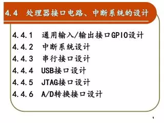
Lab. 1 – GPIO Pin control
Lab. 1 – GPIO Pin control. Using information ENEL353 and ENCM369 text books combined with Blackfin DATA manual. D Flip flop. D input is captured by the first latch of the D-Flip-flop on rising edge of a clock signal C,

Lab. 1 – GPIO Pin control
E N D
Presentation Transcript
Lab. 1 – GPIO Pin control Using information ENEL353 and ENCM369 text books combined with Blackfin DATA manual
D Flip flop • D input is captured by the first latch of the D-Flip-flop on rising edge of a clock signal C, • The output of the first latch is captured by a second D-flip-flop using an inverted clock signal • Thus the input to the D flip flop appears at its output on the falling edge of the clock after being captured on the rising edge of the clock
N flip-flops form a register • Putting 32 of this flip-flops together form a register • If this register is internal to the processor core -- system register -- R0, P0, SP, FP, CYCLES • If external to the core or on another device – not a system register
Memory mapped register • The D input values come along the memory data bus • Which register is used is controlled by the value on the memory data bus • The address of the register and the data value placed into the register is controlled by “normal” memory instructions issues by the processor
Building a radio controlled car4 Threads at least SWITCHES ON FRONT PANEL“INPUT COMMANDS: LED LIGHTS ON FRONT PANEL“CONTROLSIGNALS TO RF TRANS: PROGRAMMABLE FLAGS LED-CONTROLREGISTER FIO_FLAG_D Register EBIU INTERFACE YOUR PROGRAM RUNNING ON THE BLACKFIN int ReadSwitches( ) void WriteLED(int ) ProcessDataASM( ) subroutine VOICE A/D D/A EARPHONES A/D D/A Interrupt routine
Registers used to control PF pins • Flag Data register (FIO_FLAG_D) • Used to read the PF bits as an input -- (1 or 0) • Need to read pins PF11 to PF8, ignore all other pins values
Instructions need to access FIO_FLAG_D • Set address bus • P0.L = lo(FIO_FLAG_D); P0,H = hi(….. • Read R0 = [P0] (X) (32, 16, or 8)? • Write [P0] = R0 (32, 16, or 8)? • Select one bit R3 = 0x0100; R2 = R3 & R0; • Force one bit R2 = R3 | R0; • DON’T DESTROY VALUE R0 = R3 & R0
Flip flops • When they power up – in an unknown state – could be 1 or 0, • On power up -- processor designed to put flip-flop into known state – reset value • Whether set to 1 or 0 depends on what flip-flop output is connected to • Safety reasons – sometimes reset to 0 or reset to 1
Flip flops have set and clear capability • Make SET = 1, and toggle clock and output becomes 1 • Make SET = 0, and toggle clock and output become 0
FLIPFLOP SET FLIPFLOP CLEAR
Other GPIO Flip flopsFIO_MASKA_D and FIO_MASKB_D • If bit X = 1, tell processor to cause interrupt when FIO_FLAG_D bit X is active
Interrupt mask registersalso have their own set / clear lines • FIO_MASKA_C, FIO_MASKB_C • FIO_MASKA_S, FIO_MASKB_S
Other flip-flop group tell processor whether to interrupt on input changing or steady. This register has no meaning if interrupts are not active
Another flipflop group tells processor1) interrupt on rising / fail edge if EDGE = 12) interrupt on high level or low level if EDGE = 0
Same flipflop group tells processor1) if no interrupt then output of flipflop equals the Q output of flipflop2) If no interrupt then output of flipflop equals Q* output of flipflop
Another flip-flop group controls whether the flip-flop outputs follow the flip-flop inputs or are “high impedance” – off – no useful value
A key issue with GPIO is whether a pin is to act as an input device (bringing things in from the outside world into the Blackfin) or as an output device (sending things from the Blackfin to the outside world)
Why do you need to know how to do read (load) and write (store) on internal registers? • Flag Direction register (FIO_DIR) • Used to determine if the PF bit is to be used for input or output -- WARNING SMOKE POSSIBLE ISSUE • Need to set pins PF11 to PF8 for input, leave all other pins unchanged
Making sure that the FIO_DIR is correct for LAB. 1 – NOTE may need to change for later labaoratories Write the Blackfin assembly language instruction(s) to load the address of the internal programmable flag FIO_DIR register into pointer register P1 – then SET the Blackfin PF lines to act as inputs Design Error “Changes all pins
Notice that previous slide WARNS you about a design error in the code • We can’t do things this way as it changes all the bits in the 16 flip-flops and we only want to change 4 values in the flip-flops • The same design error is introduced into Lab. 1 Task 3 • However, the same design error is found during the TDD tests – provided to look at the test code to see what was being tested
These tests DO find the design errorand in fact explain to you why it is likely that your tests have failed. But you have to read it
This test is another indication that you have not written the code correctly. There must be 12 read and writes – not 6, not 3
We have other tests to check that your code is correct – Lab. 1 Task 4 • People come by and said ‘I have the cable correct, but it keeps on telling me I don’t’ – meaning ‘I did not look at the test to see what it was doing so Dr. Smith your Lab. Is wrong’
Task – Initialize the Programmable flag interface – 16 I/O lines on the Blackfin • Warning – could burn out the Blackfin processor if done incorrectly • You need to set (store a known value to) a number of Blackfin internal registers • Most important ones • FIO_DIR – Data DIRection – 0 for input **** • FIO_INEN – INterface ENable – 1 for enabled • FIO_FLAG_D – Programmable FLAGData register
Setting FIO_DIR to zero for “ONLY” pins 8, 9, 10 and 11. Other pins unchanged
Registers used to control PF pins • Flag Input Enable Register • Only activate the pins you want to use (saves power in telecommunications situation) • Need to activate pins PF11 to PF8 for input, leave all other pins unchanged
Making sure that the FIO_INEN is correct for enable of pins 8 to 11 Write the Blackfin assembly language instruction(s) to load the address of the internal programmable flag FIO_INEN register into pointer register P1 – then ENABLE the Blackfin PF lines as inputs Design Error “Changes all pins
Setting FIO_INEN to one for “ONLY” pins 8, 9, 10 and 11. Other pins unchanged
Task – Setting up the programmable flag interface • Follow the instructions carefully • FIO_DIR – direction register – write 0’s to bits 8 to 11 • FIO_INEN – input enable register – write 1’s to bits 8, 9, 10, 11 • Other bits leave “unchanged: • To provide a screen dump of the test result to show your code works • Use PRT-SCR button and then paste in .doc file. • In Lab. 1. the task said -- Check the following bit patterns in the manual pages 14-1 to 14-22 to make sure that I have got the patterns around the correct way.
Echoing the switches to the LEDCode in main( ) – written in C++ int main( ) { InitializeGPIOInterface( ); // Check Lab. 1 for “exact name needed” InitializeFlashLEDInterface( ); // Check Lab. 1 for “exact name needed” #define SWITCHBITS 0x0F00 // Look in MIPs notes about // using a mask and the // AND bit-wise operation // to select “desired bits” while (1) { // Forever loop int GPIO_value = ReadBlackfinGPIOFlagsASM ( ); int desired_bits = GPIO_value & SWITCHBITS; int LED_light_values = desired_bits >> 8; // Bits in wrong position WriteFlashLEDLights(LED_light_values); // to display on LEDS } }
Building a radio controlled car4 Threads at least SWITCHES ON FRONT PANEL“INPUT COMMANDS: LED LIGHTS ON FRONT PANEL“CONTROLSIGNALS TO RF TRANS: PROGRAMMABLE FLAGS LED-CONTROLREGISTER FIO_FLAG_D Register EBIU INTERFACE YOUR PROGRAM RUNNING ON THE BLACKFIN int ReadSwitches( ) void WriteLED(int ) ProcessDataASM( ) subroutine VOICE A/D D/A EARPHONES A/D D/A Interrupt routine
LEDs connected to FLASH port BACKFORWARDRIGHTLEFT??? CONTROL ON Might be connected to other thingsDON’T CHANGEBEHAVIOUR Blackfin BF533 I/O
Blackfin Memory Map • If P0 is 0x20001000thenR0 = [P0]; readsa value fromFLASH BANK 0 • If R0 is 6 andP0 is 0x1000 then[P0] = R0; placesa value intoSDRAM Blackfin BF533 I/O
Set the Bank control register • Kit documentation recommends 0x7BB0 7 cyclesnot 15 11 not 15 B = 1011 2 cycles 3 cycles IGNORE 4 cycles Blackfin BF533 I/O
Set General Control Register • Documentation says set to “0xF” for this particular FLASH chip ENABLE ALL Blackfin BF533 I/O
WriteFlashLEDASM(long in_value) • Read “LED data register” into processor data register (makes a copy) • Keep “top” 2 bits (AND operation) of copy • Keep “bottom” 6 bits of “in-par” 32-bit in_value • OR the two processor data registers • Write “modified copy” back into “LED data register” • PROBLEM “byte” read and writes Blackfin BF533 I/O
Laboratory 1 – Tasks • Download the C++ Talk-through program. • Board check -- Check that you can hear the audio output • Develop and test the code for initializing the Flash Memory and writing to the LED’s • Use the provided tests to check your code • Routine for initializing the PF GPIO lines (programmable flags) • Use the provided tests to check your code • Develop the ReadProgrammableFlagsASM( ) to read the switches • Use the provided tests to check your code • Develop the Morse code program in C++ and ASM