Download
1 / 10
100 likes | 304 Vues
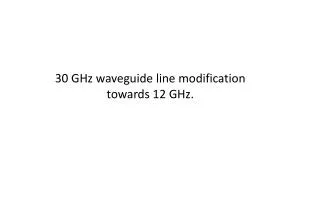
30 GHz waveguide line modification towards 12 GHz. Current 30 GHz layout. Modification towards 12 GHz . Overmoded 90 bend. CTF3. H10-> H01 mode converter (CEA). Mode converter. Ø36 ->Ø50 matched taper (CEA) . Directional coupler. RF/vac. Gate valve.

E N D
Current 30 GHz layout Modification towards 12 GHz Overmoded 90 bend CTF3 H10-> H01 mode converter (CEA) Mode converter Ø36 ->Ø50 matched taper (CEA) Directional coupler RF/vac. Gate valve Ø50 circular waveguide (existing line) CTF3 Customized 90 degrees WR90 H bend The gate valve and vacuum port are the new components for our group. I recommend to adopt our fresh designs (see next page) for their low price and high performance. Otherwise we can use already existing gate valve designed by CEA (quite bulky and expensive it also requires two mode converters) and pumping ports being design for stand along power source (they are quite long!). TBD. CTF2 Vac. Pumping port CTF2
New components based on existing/tested RF designs CLIC choke mode flange Mini UHV gate valve Compact RF/vacuum gate valve = + Compact RF/vacuum pumping port (design) To be re-placed by vacuum flange Existing T-splitter pumping port
The components table CEA based CEA + CERN H10 -> H01 Mode converters: Circular tapers: Gate valves: Pumping ports: Directional couplers: RF load 8 (incl. 4 for 2 gate valves) (prototypes exist, needed to be ordered from industry) 4 (prototypes exist, needed to be ordered from industry) 4 (prototypes exist, needed to be ordered from industry) 4 (prototypes exist, needed to be ordered from industry) 2 units. Needed technical design 2 bodies (prototypes exist, needed to be ordered from industry) 3 (prototypes exist, needed to be ordered from industry) 3 units. Needed technical (little) design 2 units 1 units The additional WR90 waveguide straight sections, bends and splitters to connect the structure and klystron’s line are not counted, should be defined when complete layout is ready.
Other developments towards 5 MW klystrons cluster and new 50 MW stations
Compact SLED-type X-band pulse compressor. Design & components by F. Peauger, CEA. From Klystron H01 Mode Converter F36mm Hybrid Short circuit + pumping port Iris To Accelerating Structure H0 1 31 Cavity H01 Circular Taper (F36mm→ F50mm) SLAC-type Double height 3 dB hybrid H01M ‘rugby’ cavity Mode: H0,1,31 Length: 420mm Max. : 110 mm Q0: 1.82x10⁵ (HFSS) H01 tapers (36->50) KEK-type compact H10-H01 mode converter These components were designed and fabricated by CEA as a French in-kind contribution to the 12 GHz klystron station waveguide network at CERN Currently we anticipating to furnish 6x50 MW stations. With development of a klystron cluster and collaboration with KVI (and others?), another 6 klystron could appear, thus at least 12 pulse compressors are needed to be build. CERN-CEA design uses existing components (mode converter, taper and hybrid). It needs technical support to design of the cavities and the whole system to be complete. The work should be done in collaboration with CEA. We should not consider other supplier (GYCOM) due to steady decay of their production quality.
The components table for x12 pulse compressors H10 -> H01 Mode converters: Circular tapers: Cavities: Hybrids: 24 (prototypes exist, needed to be ordered from industry) 24 (prototypes exist, needed to be ordered from industry) 24 bodies (to be designed) 12 (many prototypes exist, needed to be ordered from industry) • Additional: • Every klystron channel should be equipped with 2 gate valves and 2 pumping ports, so we should foresee extra 24 valves and 24 pumping ports. • For diagnostic and power termination at least 12 directional coupler and 12 RF loads will be needed.
Overall summary of components I’ve considered that for the valve and pumping port we can use our new design H10 -> H01 Mode converters: 28 Circular tapers: 28 Hybrids: 12 Gate valves: 26 Pumping ports: 27 Directional couplers: 14 RF loads: 13
Compact variable splitter/attenuator The existing (GYCOM) attenuators are bulky , have 10% Ohmic losses and ~6 ns group delay. In the future we will need such a devices to connect the existing TBTS PETS with CLEX module PETSes. The new attenuator design is based on CLIC components. The other place for splitter to be used is an interface between structure testing area and dog-leg RF line. At least 3 units will be needed. CLIC E-plane hybrid CLIC variable reflector
![Frequency [GHz]](https://cdn1.slideserve.com/3024092/slide1-dt.jpg)


![Frequency [GHz]](https://cdn3.slideserve.com/6756635/slide1-dt.jpg)