Download
1 / 28
290 likes | 643 Vues
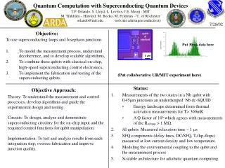
qubit & readout. 5 m m. Quantum Computation with Superconducting Quantum Devices T.P. Orlando, S. Lloyd, L. Levitov, J.E. Mooij - MIT M. Tinkham – Harvard; M. Bocko, M. Feldman – U. of Rochester orlando@mit.edu web.mit.edu/superconductivity. 7/28/02.

E N D
qubit & readout 5 mm Quantum Computation with Superconducting Quantum DevicesT.P. Orlando, S. Lloyd, L. Levitov, J.E. Mooij - MITM. Tinkham – Harvard; M. Bocko, M. Feldman – U. of Rochester orlando@mit.edu web.mit.edu/superconductivity 7/28/02 Put 30mk data here Objective: To use superconducting loops and Josephson junctions • To model the measurement process, understand decoherence, and to develop scalable algorithms, • To combine these qubits with classical on-chip, high-speed superconducting control electronics, • To implement the fabrication and testing of the superconducting qubits. (Put collaborative UR/MIT experiment here) • Status: • Measurements of the two states in a Nb qubit with 0.45mm junctions an underdamped Nb dc-SQUID : • Energy landscape determined from thermal activation measurements for T> 300mK • A Q factor of 106 which agrees with measurements of the Rsubgap > 1 MW. • Al qubits: Measured relaxation time ~ 1 ms • SFQ components (delay lines, DC/SFQ, T-flip-flops) measured at low current density and low temperature. • Modeling the environmental coupling to the qubit and the measurement process • Scalable architecture for adiabatic quantum computing Objective Approach: Theory: To understand the measurement and control processes, develop algorithms and guide the experimental design and testing. Circuits: To design, analyze and demonstrate superconducting circuitry for the on-chip input and the required control functions for qubit manipulation. Implementation: To test and analyze results from each integration step; oversee fabrication and improve junction quality.
Participants and Collaborators MIT Seth Lloyd: Lin Tian, Bill Kaminsky Leonid Levitov; Terry Orlando: Ken Segall Donald Crankshaw Daniel Nakada, Janice Lee Bhuwan Singh, David Berns Harvard University Michael Tinkham: Nina Markovic, Sergio Valenzuela University of Rochester Mark Bocko & Marc Feldman Jon Habif, Pavel Rott Xingxiang Zhou Gui-Zhen Zhang, Michael Wulf MIT Lincoln Laboratory Karl Berggren & Jay Sage TU DELFT Johan Mooij & Kees Harmans Alexander ter Haar University of Munich Frank Wilhelm: Markus Storcz AFRL Jeff Yepez This work is supported in part by the AFOSR grant F49620-01-1-0457 under the DoD University Research Initiative on Nanotechnology (DURINT) program and ARDA, and in part by the AFOSR/NM and also by the NSA and ARDA under ARO grant number DAAG55-998-1-0369. The Type II computing is funded by AFOSR/NM.
Lincoln Laboratory (fabrication and type-II computing) Delft (off-chip experiments, Al qubits, tight collaboration, theory) TRW (fabrication source) MIT (MIT/Cambridge Consortium, NSF Center, Type II computing) Univ. Munich (Frank Wilhelm) Theory AFRL (Yepez) Type II computing SQUBIT European Project Collaborations
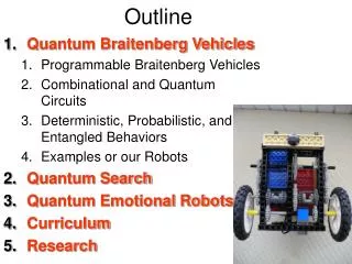
General Overview (Terry Orlando) Introduction Highlights of recent results Future work Implementation Review (Ken Segall) Circuits Review (Marc Feldman) Experiments from Delft (Kees Harmans) Theory Review (Seth Lloyd) Outline
|0 IcirEi |1> 0.5 Fext (F0) Persistent Current Qubit This qubit design uses a superconducting loop interrupted by three Josephson Junctions. The two lowest energy states, which serve as the |0> and |1> states of the qubit, have circulating currents in opposite directions, with opposite magnetic fields of ~0.001 0. current j3 v 1 j1 j2 2 ƒ1 Rotating the qubit will require flux oscillations at the frequency of the energy difference. The Rabi frequency depends on the magnitude of the flux oscillations.
I+ V+ Ib qubit & readout Cs Ic CJ Z0 0.45m 5 mm 0.55m 1.1m 1pF 1.1m 1pF qubit I- V- ~ j1 ~ j2 Quantum Computation with Superconducting Quantum DevicesT.P. Orlando, S. Lloyd, L. Levitov, J.E. Mooij - MITM. Tinkham – Harvard; M. Bocko, M. Feldman – U. of Rochesterin collaboration with K. Berggren, MIT Lincoln Laboratory 7/28/02 • Persistent current qubit fabricated in Nb with submicron junctions • Two states seen in measurement (thermal activations and energy levels) Fabrication modeling, and measurements
EJ = 4200 meV Q = 2x10⁶ Thermal Activation Theory Condition for <Isw> = 0 Thermal rate with damping (Energy diffusion regime) Energy barrier linear in flux • EJ indicates junctions are small (0.55 mm) • Q suggests long relaxation times (T1 ~ Q/w0 ~ 4 ms)
9.711 Ipc 8.650 6.985 5.895 4.344 (0.4 nA per division) 3.208 2.013 SW 1.437 I ~ 1.120 0.850 0.498 0.500 0.502 (F0) F ext 3 mm Macroscopic quantum superposition in a Josephson junction loop Delft University of Technology & DIMES The Netherlands MIT Cambridge Caspar van der Wal, A. Ter Haar, Kees Harmans, Hans Mooij T. Orlando, L. Levitov, S. Lloyd • Superposition of states observed • Relaxation time 5 msec, • Dephasing time 0.1 msec MIT
Relaxation time Measured relaxation time ~ 1 ms
Inductance measurement - it’s exactly right Tested (4.2 K) analog and digital devices on LL fabricated chips (500 A/cm2 nominal) dc-SQUID coupled to large inductive loop Small junction I-V’s ~ 0.4 x 0.4 µm RSFQ test circuit dc-sfq, JTL’s, confluence buffer, splitter, JTL clock ring, sfq-dc SFQ Results on QC2 Add UR logos, reference here
Test Results Operation of the circuit on the previous page. Each cycle of the input waveform introduces one SFQ pulse to the circuit. The output flips its voltage state at each arriving pulse. ~350 bits/sec. ~3.5 kbits/sec. Add UR logos, reference here
On-chip Control for an RF-SQUID M.J. Feldman, M.F. Bocko, Univ. of Rochester
Offset charge fluctuations Quasiparticles Q > 104 Bias current fluctuations Sources of Error in Superconducting Qubits Decoherence from the environment (use error correction) Dephasing sources (use “spin echo” techniques) • Coupling to nuclear spins • Diople-dipole coupling Coherent error sources (use dynamic pulse control) • Coupling to higher levels • Two-bit gate coupling Lin Tian, L. Levitov, et al., “General Theory of Dephasing for the Qubit,” Quantum Mesoscopic Phenomena (2000)
I b Cs Ic CJ Z0 ~ ~ j2 j1 qubit Model of Measurement Induced Decoherence Spin-Boson Model gives Lin Tian, Seth Lloyd, T. Orlando PRB (2001)
Adiabatic QC More theory slide
Type II Quantum Computing:1-D Algorithm where P is occupancy probability Ψ1,aΨ2,a Ψ3,aΨ4,a Ψ5,a Ψ6,a · ·· ··· Ψ1,b Ψ2,b Ψ3,bΨ4,b Ψ5,bΨ6,b Initialize Φ1Φ2 Φ3Φ4 Φ5 Φ6 · ·· ··· Collide P’1a P’2a P’3a P’4a P’5a P’6a · ·· ··· P’1b P’2b P’3b P’4b P’5b P’6b Measure P’1a ← P’2a←P’3a←P’4a ←P’5a←P’6a P’1b → P’2b →P’3b→P’4b →P’5b →P’6b Stream*
Measurement Iqubit bias Imeas bias f1 f2 Vosc bias fosc
Quantum Computation with Superconducting Quantum DevicesT.P. Orlando, S. Lloyd, L. Levitov, J.E. Mooij - MITM. Tinkham – Harvard; M. Bocko, M. Feldman – U. of Rochester orlando@mit.edu web.mit.edu/superconductivity 7/28/02 • Progress on last year’s objectives • Measurements of the two states in a Nb qubit with 0.45mm junctions and underdamped Nb dc-SQUID : Energy landscape determined from thermal activation measurements for T> 300mK, and a Q factor of 106 and Rsubgap > 1MW. • SFQ devices at 300 mK and for current densities < 200 Amps/cm2 • Al qubits: Measured relaxation time ~ 1 ms • Scalable architecture for adiabatic quantum computing with superconductors • Research plan for the next 12 months • Measurement of on-chip spectroscopy of a single qubit • On-chip timed oscillator control of a single qubit • Spectroscopy of two-coupled qubits • Resonance method of measurement of the state of the qubit (with Delft) • Set up Dilution Refrigerators • Theory here • Long term objectives (demonstrations) • - Combine 3 to 5 superconducting qubits with on-chip control electronics • - Measure decoherence in multiple-qubit systems • - Develop algorithms adapted to superconducting electronics • - Explore quantum control to correct qubit dynamics
Summary Slides of Results, Circuits, and Publications Not to be presented
Implementation: Subgap resistance of submicron Nb junctions > 1 MW at low temperatures LL Resistors remain at 30 mK Measurements of the two states in a Nb qubit with 0.45mm junctions an underdamped Nb dc-SQUID : Energy landscape determined from thermal activation measurements for T> 300mK A Q factor of 106 which agrees with measurements of the Rgap > 1 MW. Delft Experiments: Spectroscopy of superposition states Developing of gradiometer qubits to lessen flux noise Experiments on decoherence times and noise (Delft) Installation of Dilution Refrigerators underway at MIT and UR Results to Date
Circuits: SFQ T-Flip-Flop demonstrated at 300 mK and for current densities < 200 Amps/cm2 Demonstration of Flip-Chip inductive coupling On-chip coupling of JJ Oscillator Design of MQC experiments on-chip Developing resonant measurement scheme Other results here
Theory: Theory of persistent current qubit Calculation of intrinsic decoherence mechanisms and sources of errors Method to overcome off-resonant excitations Modeling of decoherence of coupling and measuring circuits- circuit model formulation Modeling of measurement process with DC SQUID Exploration of coupling schemes for qubits Scalable architecture for adiabatic quantum computing with superconducting
I. Circuits and Components That Have Already Been TestedA. Simple Control Circuits:1. On-chip DC-SQUID oscillators have been tested and sufficient inductive coupling to another circuits has been demonstrated. These oscillators however only operated around 3 GHz, so oscillators with variable frequency are now being fabricated. (MIT)2. Demonstration of inductive coupling between separate chips for use in coupling qubits with control circuits fabricated on different chips (Lincoln).3. Theoretical modeling of the effect of these simple control circuits on the decoherence of the qubit was included in the designs of the oscillators and measuring system.(MIT/Delft/Rochester)4. Test at 4.2K of an RF SQUID coupled to a superconductive comparator with readout to room temperature (Lincoln).5. Fixed-current superconducting loops, for magnetic flux biasing (Rochester)B. Complex Circuit and components1. The following components have been designed, fabricated,and tested at 4.2 K. a. DC/SFQ and SFQ/DC converters (Rochester) b. DRO memory cells (Rochester) c. T-Flip-flops (Rochester) d. Chains of up to 16 T-Flip-flops as counters. (Rochester) e. SFQ clocks (pulse oscillators) of fixed frequencies designed from 5 to 40 GHz. (Rochester) f. Pulse splitters and combining buffers (Rochester)
II. Types of Circuits and components that are being fabricated on QC3 (scheduled for completion in later this year.)A. Simple Circuits:1. On-chip DC-SQUID oscillators to work in the 5-15 GHz regime (some connected to detectors and some to qubits to do on-chip spectroscopy) (MIT)2. On-chip SFQ microwave oscillator to work at 8 GHZ regime. (some connected to detectors and some to qubits to do on-chip spectroscopy) (Rochester/MIT)3. A qubit coupled inductively to a coplanar waveguide. Using an external microwave generator, operating at 1-20GHz, it is possible to map the energy separation between the lowest two energy levels. (Lincoln and MIT)B. Complex ExperimentsList experiments on QC3 and explain briefly whose circuit and why the circuit is important.1. An NDRO memory cell, similar to a DRO cell but with a non-destructive read-out, is being fabricated. Asuccessful test will allow the timed oscillator experiment (Rochester)2. Timed oscillator experiment -- by using two out-of-phase counter and an NDRO memory cell, we can make a variable duty cycle oscillator to drive a qubit with a SQUID detector controlled off-chip. (Rochester)3. Qubit readout experiments a. QFP Comparators coupled with varying strengths to RF SQUID qubits (Lincoln) b. QFP Comparators coupled to persistent-current qubits (Lincoln) c. SFQ Comparators coupled to rf SQUID qubits and to testlines (Rochester)
C. Full Quantum Experiments Circuits (more-than-complex circuits) 1. Superposition-state time evolution experiment using rf SQUID qubit. This design has all-SFQ inputs and outputs, all on-chip; but off-chip timing. (Rochester) 2. Superposition-state time evolution experiment using single-Josephson-junction qubit (inspired by Martinis and Han experiments), with on-chip SFQ control circuits. Specifically designed to be portable to TRW fabrication. (Rochester)
Publications 1. Design of Persistent Current Qubit J. E. Mooij, et al., Science, 285, 1036, (1999) T. P. Orlando, et al., PRB 60, 15398 (1999) 2. General Theory of Dephasing for the Qubit Lin Tian, L. Levitov, et al., in Quantum Mesoscopic Phenomena (2000) 3. Pulse Scheme to Decouple Higher Levels Lin Tian and S. Lloyd, PRA 62, 50301 (2000) 4. Measurements of the Qubit Energy Levels C. van der Wal, C. Harmans, J. E. Mooij, et al. Science 290, 773, (2000) 5. Inductance Effects on the Qubits D. Crankshaw, E. Trias, et al. IEEE Trans. Applied Supercond. 11, 1223, (2001) 6. Fabrication of Nb Qubits and Circuits K. Berggren, D. Nakada, et al.Proceedings of the International Conference on Experimental Methods in Quantum Computation, 2001. Rinton Press. 7. Modeling of the Measurement Process C. van der Wal, F. Wilhelm, et al.,to be published Lin Tian, S. Lloyd, and T. Orlando, et al.,to be published D. Crankshaw, et al.,to be published