Download
1 / 23
280 likes | 765 Vues
The Use and Management of TRITIUM in ITER. R. Lässer. Content. Introduction Inner and outer Fuel Cycle of a Fusion Reactor Radiotoxicity of tritium Tritium in gases, liquids and metals Preconditions of safe processing tritium Tritium experiments in Tokamaks

E N D
The Use and Management of TRITIUM in ITER R. Lässer R. Laesser, F4E ITER Department
Content • Introduction • Inner and outer Fuel Cycle of a Fusion Reactor • Radiotoxicity of tritium • Tritium in gases, liquids and metals • Preconditions of safe processing tritium • Tritium experiments in Tokamaks • The Deuterium Tritium (DT) Fuel Cycle • Subsystems of the DT Fuel Cycle • Storage and Delivery System, Long Term System • Vacuum Pumping Systems • Tokamak Exhaust Processing System • Isotope Separation System • Water Detritiation System • Topics addressed in WP7 (Tritium Plant) during ITER Design Review • Tritium building layout • Modification of HVAC, ADS and VDS • Tritium Tracking Strategy • Tritium in Plasma Facing Components • Tritium Processing in Test Blanket Modules • Tritium Processing in DEMO • Acknowledgements R. Laesser, F4E ITER Department
The Inner and Outer Fuel Cycle of Fusion Reactors • Among the potential fusion reactions technically most suitable is the reaction between deuterium and tritium 2D + 3T→ 4He (3.5 MeV) + 1n (14.1 MeV) • 0.016 at% Deuterium are contained innatural water. • Tritium needs to be produced. • 56 kg tritium is required per GWyof fusion power. • About 100 g tritium is produced peryear in a standard CANDU fission unit. • Breeding of tritium is necessary in a fusion reactor: n + 6Li → T + 4He n + 7Li → T + 4He + n • 20 to 25 kg tritium will be needed for operation of ITER. • A few kg tritium will be always needed for starting a power fusion reactor. TES Tritium Plant 08/29 R. Laesser, F4E ITER Department
Tritium decays: 3T → 3He+ + β- + ν + 18.6 keV. T1/2 = 12.3 y Tritiated hydrogen (HT, DT, T2) breathed-in by the lounges leads to a local β- dose, but is almost completely breathed out. Also the uptake of hydrogen (tritium) through the skin is very small. Q2 stands for: H2, HD, HT, D2, DT, T2. Tritiated water vapour (HTO, DTO, T2O) is readily incorporated via the lounges and the skin. Within a few hours tritiated water is homogeneously distributed in the body fluids and causes a whole body dose which can easily be determined by measuring the tritium concentration in the urine or in the breathed out air. (Q2O stands for: H2O, HDO, HTO, D2O, DTO, T2O. Biological half life: about 10 days. Organically bound tritium: half life time: months. Tritiated water is approximately 25000 times more radiotoxic than tritiated hydrogen. In consequence: Tritium is one of the least radiotoxic nuclides. Tritium can induce X-rays. Radiotoxicity of Tritium R. Laesser, F4E ITER Department
Effects of Tritium in Gases and Liquids • Tritium in gases • Composition and pressure of tritiated gas mixtures change due to tritium decay: • 3He is generated. • Radicals, new and ionized gas molecules can be created by the decay electrons. Even solid matter such as plastics can be produced if hydrocarbons are present. • Tritium in water • At high T-concentrations in the water radiolysis occurs with generation of oxygen, hydrogen and tritiated peroxide. Storage of highly tiritiated water needs a recirculation loop with small hydrophobic catalyst to recombine hydrogen and oxygen again (5 liter of HTO create about 20 liter of DT per day). • Tritium gas in contact with metal surfaces • Metal oxides can be reduced by tritium resulting in clean metallic surfaces (leading to diffusion limited permeation (not any more surface limited)). As a consequence of these reactions the purity of the tritium gas stored in a container will deteriorate. R. Laesser, F4E ITER Department
Tritium compatible materials/equipment:No plastics / oil. Yes: metals / ceramics. • Confinement of tritium: • Primary confinement: prevents T-releases into the areas accessible by workers by means of barriers: primary containment can be surrounded by intermediate volumes or secondary containments (glove- or valve box). • Secondary confinement:prevents T-releases into non-controlled/non-supervised areas and into the environment. • Simple design and use of well proven techniques: The design must allow easy maintenance and repair. • Stringent installation and commissioning procedures: Stringent leak tightness requirement: <10-10 Pam3/s for facilities and <10-11 Pam3/s for components. • Strict operational and local procedures. • Equipment to be installed in well ventilated buildings. • Tritium inventories to be limited and segregated as far as possible. PRECONDITIONS FOR SAFE PROCESSING TRITIUM R. Laesser, F4E ITER Department
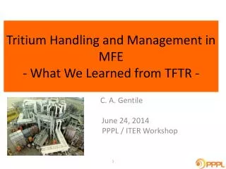
TRITIUM EXPERIMENTS IN TOKAMAKS • Preliminary Tritium Experiment (PTE) at JET: end of 1991 • First DT experiments in a fusion machine, limited number of plasma shots, less than 0.2 g of tritium on site. No recycling of tritium. • Tritium Processing during Tritium Campaign at TFTR (1994-1997) • Maximum site inventory 5 g, 78 g were supplied to NBI, most of the T-processing was done at other US site, very limited recycling. • Tritium Processing during Deuterium Tritium Experiment (DTE) at JET in 1997 • Tritium amount on site: 20 g, Active Gas Handling System (AGHS =JET Tritium Plant) supplied 100 g T, 11.5 g was highest tritium amount trapped in tiles + flakes. Tritium was recycled five times. • Trace Tritium Experiment (TTE) at JET in October 2003 • Operation of AGHS during TTE in similar way as during the DTE, however only very small amounts of tritium were injected into the machine. R. Laesser, F4E ITER Department
Hydrogen/tritium storage in large JET U-beds, cracking of impurities T2 supply from U-beds + injection via NBI 345 liter vessel used for (pVT-c) accountancy 4 U-beds T 2 U-beds PTE at JET 1991 Very simple Tritium Processing Systems (all equipment shown) 6Ø cm Cryogenic pump: 4.2K cold finger, He dewar was moved by a lifting platform R. Laesser, F4E ITER Department
DTE: Use of Active Gas Handling System (AGHS): 1997 Stack Bridge: Cryogen + active gas lines AGHS Building Cryogenic Forevacuum System Control Room Torus Basement AGHS R. Laesser, F4E ITER Department
The Deuterium Tritium (DT) FUEL CYCLE of ITER • Tritium fuelling via • Pellet injection, • Gas puffing. • NBI not used for tritium injection. Closed DT loop required especially with respect to tritium as tritium releases into the environment must be kept as low as reasonable achievable (ALARA). R. Laesser, F4E ITER Department
CN, EU, JA, US, Fund Korea, Fund The ITER DT Fuel Cycle Korea, Fund EU EU, Fund EU, Fund US, Fund All Participating Teams EU JA,Fund Leak Detection All Participating Teams, Fund Fund EU, US Fund 10/29 R. Laesser, F4E ITER Department
Tritium Plant: 2001 baseline R. Laesser, F4E ITER Department
Nuclear Buildings The ITER BUILDINGS The ITER ("the way") Project (2/3) 04/29 R. Laesser, F4E ITER Department
Subsystems of the DT Fuel Cycle • Storage and Delivery System (SDS) and Long term Storage (LTS) • Vacuum Pumping Systems: Cryo- and Roughing Pumps • Tokamak Exhaust Processing System (TEP) • Isotope Separation System (ISS) (throughput 200 Pam3/s) • Water Detritiation System (WDS) • Analytical System (ANL) • Fuelling Systems • Pellet Injection • Neutral Beam Injection • Gas Puffing • Atmosphere and Vent Detritiation Systems Fuelling rates: • 120 Pam3/s for 3000 s (about 1 kg DT/h), • 160 Pam3/s for 1000 s, • 200 Pam3/s for 400 s, • Fuelling rate can increase for short times 230 Pam3/s (for ELMs pacing). R. Laesser, F4E ITER Department
Storage and Delivery System + Long Term System (KO) • Purpose of Storage and Delivery System (SDS) • To store tritium and deuterium in storage beds (70 g tritium/bed), • To supply gases of the requested compositions and flow rates to the fuelling systems, • To perform accountancy by in-bed calorimetry (accuracy: ~1% for fully loaded bed) and (pVT-c) measurements, • To collect He-3. • Purpose of Long Term System (MBA-2 in ITER) • To store the tritium in 10 getter beds (without accountancy) to keep total tritium inventory in FC at low value. • To import and account tritium supplied to ITER, • Safest storage technique of tritium today is the use of metal getter beds with high affinity to hydrogen. • Advantages: Storage beds can act as pumps at RT and compressors at higher temperatures. Negligible tritium permeation at RT. Purity of the dissolved tritium is conserved. Removal of 3He from tritium possible. High storage capacity per volume. In-bed calorimetry possible. • Disadvantages: needs heating to temperatures around 400-500°C. Low thermal conductivity of metal hydride powder critical for achieving high hydrogen supply rates. Powder is pyrophoric. Possibility of He-blanketing. Large volume increase of metal after hydriding due to power production. Creation of tritiated waste. R. Laesser, F4E ITER Department
Storage and Delivery System + Long Term System (KO) • ITER Getter beds still to be optimized (requiring thermomechanical / hydraulic calculations) for • Fast supply, • Fast pumping, • Space needed for hydrided materials, • Accurate accountancy, • Fast cooling. • IO and Korea still prefer ZrCo instead of uranium (U). ZrCo disproportionates in the presence of higher hydrogen pressures: (2 ZrCo + H2 = ZrCo2 + ZrH2). Pumps are requested to keep the pressure in the beds low to avoid disproportionation. • Reproportionation is possible under vacuum at higher temperature. Memory effects exist. • No long term experience of ZrCo with tritium exist. However tritium experience with U is huge. U has very broad horizontal plateau pressure, whereas this pressure increases in the case of ZrCo. • EU strongly in favor of using uranium as getter material. R. Laesser, F4E ITER Department
Pump connection flange Valve pneumatic actuator 80K louvre baffles 4.5K cryosorption panel circuit Integral inlet valve Vacuum Pumping Systems (EU) • Vacuum Pumping: • 8 Torus-, 2 cryostat cryopumps • 3 HNB-, 1 DNB cryopumps • Cold Valve boxes + cryojumpers Purpose: Pumping Torus (153 Pam3/s), cryostat and HNB and DNB facilities. Pumping tests with a half size model cryopump successfully finished. Final design of a full prototype torus cryopump (PTC) in progress: 1.8 m diameter; 2.1 m long; 11.2 m2 charcoal coated, 0.8 m diameter inlet valve with 0.5 m stroke to modify pumping speed. Prototype Torus Cryopump No regeneration required during short plasma pulses (450 s). During long shots (3000 s) quasi-continuous regeneration occurs up to 100K for release of helium and hydrogen to recycle the released hydrogen. R. Laesser, F4E ITER Department
Ion Source Neutraliser Cryopanels Schematic of HNB 1 section 1 module with 4 sections Vacuum Pumping Systems (EU) • Regeneration separates gas stream: • 80K: Q2 and He (Ne): every 150 seconds. • 300K: Air-like impurities (CO, CO2, lower CnQm), daily regeneration of all cryopumps (overnight). • 470K: Water-like impurities (higher CnQm), regeneration of one cryopump (overnight). HNB cryopump Rough Pumping System: Combination of Roots pump (1 off 4200 and 2 off 1200 m3/h and screw- or piston pumps). Separation of pumping and oil filled volumes by special seals (e.g. ferrofluidic seals). 5K Proposal to freeze out the highly tritiated water (from the 470K regeneration) upstream of Roots pumps to avoid condensation. 80 K R. Laesser, F4E ITER Department
Tokamak Exhaust Processing (TEP) System (US) • Purpose of TEP • to treat all gases from various systems (NBI, TP, Diagnostics) to • extract hydrogen in water vapour and hydrocarbons, • discharge the hydrogen depleted streams via vent detritiation (TEP release conditions relaxed from 1 Ci/m3 to 200 Ci/m3). • Replacement of carbon by W will simplify the requirements of TEP as hydrocarbons will be no longer the dominant impurities. • Main components of TEP • Permeators to extract the unburnt fuel (hydrogen) from the gas mixtures, • Catalysts to crack the hydrogen containing molecules and permeators to extract the produced hydrogen, • Pumps for circulation of the gases. • Unresolved topic: Processing of highly tritiated water R. Laesser, F4E ITER Department
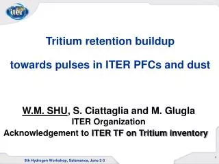
Highly Tritiated Water • 1 kg DTO contains 143 g tritium or 1.4 MCi. • High tritium concentrations in water are expected from various sources such as 470K regenerations of cryopumps, during dedicated phases for recovery of the tritium trapped inside the VV and from Hot Cell. R. Laesser, F4E ITER Department
Processing Options of Highly Tritiated Water • Reduction of DTO to DT by means of • Electrolysis of DTO (1.4 MCi/kg) • Electrolysis of liquid water very difficult above 2000 Ci/kg, leads to further enrichment. • Metals such as magnesium, uranium or iron • Reaction with iron is not complete (75% conversion at 500°C), however reversible • Decontamination factor limited to about two orders of magnitude • Exothermic reaction with magnesium or uranium • Highly tritiated waste (Mg / MgO containing MgO2DT) • Carbon monoxide (water gas shift reaction): CO + DTO = CO2 + DT • Isotopic exchange of DTO with H2 to DT and H2O • Exchange in liquid water (Liquid Phase Catalytic Exchange (LPCE)) • Exchange in vapor phase (Vapor Phase Catalytic Exchange (VPCE)) 24/29 R. Laesser, F4E ITER Department
72 g/h H2O 4.2 g/h DTO, 5.9 kCi/h Use of Isotopic Exchange: DTO + H2 = H2O + DT • Use of Liquid Phase Catalytic Exchange (LPCE): Outline conceptual design • 4,2 g/h (100 g/day) DTO vapor flow rate • 72 g/h H2O liquid water feed flow rate (mixing factor 20) • Water for mixing could be tritium contaminated • Moisture in HT to be condensed and returned • 48 g/h H2 flow rate (molar ratio 6) • Trade off to mixing factor, column length, outlet concentration • H2 to be added could also be slightly contaminated • 80 g/h (4.2 mol/h) tritiated water flow rate at 150 Ci/kgto Water Detritiation System (capacity > 20 kg/h @ 10 Ci/kg) • Column height about 4 m, column diameter about 3 cm • Upper section of the column to be easily replaceable • Catalyst lifetime could be limited due tohigh tritium concentration (no problem for VPCE) LPCE column 80 g/h Q2O/h, 12 Ci/h or electrolyser 25/29 R. Laesser, F4E ITER Department
ISS Isotope Separation System (EU) • Isotope Separation System (ISS) utilizes cryogenic distillation and catalytic reaction for isotope exchange to produce the required hydrogen isotope gas mixtures. • Purpose of ISS • To accept the hydrogen isotope mixtures (up to 200 Pam3/s) from TEP, NBI and WDS. • To produce the required pure deuterium (<0.02% T, <0.5% H) and 90% T/10% D gas mixtures for the users and SDS. • To transfer detritiated (<0.1 ppm T) hydrogen to WDS for further detritiation and final release. 4 columns installed in cold- box R. Laesser, F4E ITER Department