Download
1 / 20
200 likes | 448 Vues
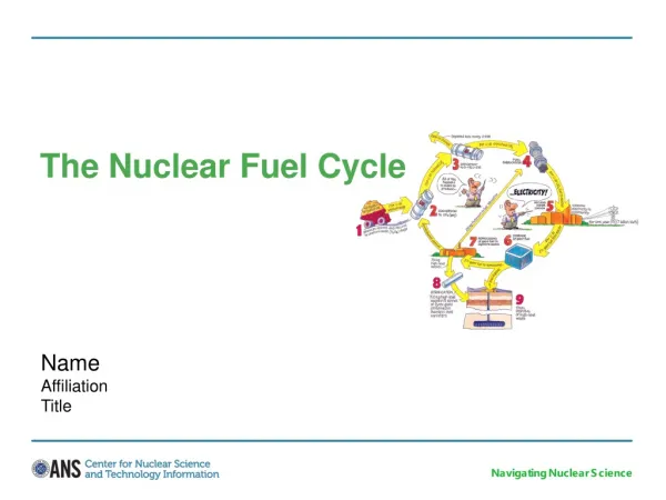
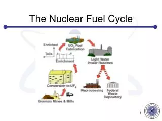
ITER Tritium Fuel Cycle Modeling. Scott Willms and Bill Kubic Los Alamos National Laboratory Fusion Nuclear Science and Technology Workshop UCLA August 2, 2010. Outline. Tritium Processing modeling history TEP modeling Consideration of next steps. Tritium processing modeling history.

E N D
ITER Tritium Fuel Cycle Modeling Scott Willms and Bill Kubic Los Alamos National Laboratory Fusion Nuclear Science and Technology Workshop UCLA August 2, 2010
Outline • Tritium Processing modeling history • TEP modeling • Consideration of next steps
Uses for tritium processing models • Component design • System design • Parameter regression • Technology trade-off studies • Hazard characterization and analysis • Requirements determination • Control system development • Experimental development augmentation • Design documentation • Operator training
TEP modeling overview • TEP model used for: • Component regression from experimental data • Technology selection • Component sizing • TEP models include: • Component models • Detailed understanding of component performance • System models • Overall process performance
Aspen property library Aspen Plus Steady state model Kinetic model data Basic flowsheet data Aspen Dynamics Dynamic model Aspen Dynamics library Aspen Custom Modeler User defined model Custom TEP library Modeling tools relationship
TEP models completed • Modules • Permeator (ACM) • PMR (ACM) • PERMCAT (stand-alone) • Vacuum Pumps (ACM) • Ambient molecular sieve bed (ACM) • Cryogenic molecular sieve bed (ACM) • Dynamic feed generator (ACM) • Molecular and transition flow conductance model (ACM) • Sub-Systems • Hydrogen-like processing • Air-like processing • Water-like processing
Examples of module bechmarks Comparison of permeator model with data of Willms et al. (1993) Comparison the model with LANL data for a Normetex 15 backed by an MB-601
Aspen system models used to optimize design • Can account for system interactions in the design process • Permeator-pump interactions • PMR-pump interactions • Multistage permeator pump performance • Easy to modify PFD to reduce equipment sizes and minimize pumping requirements • Can base sizing calculations on overall system performance
Permeator Train Breakthrough Most Common Operations Example - Permeator Optimization • Vary the number of first stage pumps • Determine tritium release from third (final) stage peremator • Determine breakthrough area • Determine number of pumps and permeator area based on point of dimishing returns • Six MB-601 pumps for first stage • 3 m3 of membrane area for first stage • Evaluate system margin • Margin based on overall system performance and not individual units Tritium release from third stage as a function of number of first stage pumps First stage area as a function of number of first stage pumps Tritium release from third stage as a function of feed rate
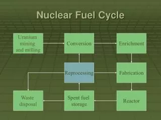
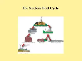
DT Major flow paths for ITER Fuel Cycle during DT
Next steps • Past modeling efforts have laid an excellent foundation for the next work that needs to be performed • The ITER TEP modeling effort has laid an excellent template for future work • Major development needed includes: • Models of ITER sub-systems (expect for TEP) • ITER Fuel Cycle model • ITER TBM modeling • Fusion Nuclear Science Facility model • Benchmarking
Summary • Computer modeling has been an important component of tritium processing development • Recent ITER TEP modeling was not only successful in itself, but lays an excellent template for future modeling work • There are a number of current and future projects which would benefit greatly from further modeling work