Download
1 / 39
390 likes | 621 Vues
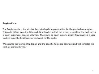
Fuel-Air Modeling of Brayton Cycle. P M V Subbarao Professor Mechanical Engineering Department. Exact Modeling of Cycle is a first step for Energy Conservation…. Brayton Cycle for Power Generation. Isentropic Compression Process. For a infinitesimal compression process:.

E N D
Fuel-Air Modeling of Brayton Cycle P M V Subbarao Professor Mechanical Engineering Department Exact Modeling of Cycle is a first step for Energy Conservation…..
Isentropic Compression Process For a infinitesimal compression process:
g cp cv
P2 P1+(n-1)dP dTn P1+3dP P1+2dP P1+dP dT2 dT1
Explicit Method: For an infinitesimal compression from p1:
Explicit Method: For another infinitesimal compression from p+dp: For another infinitesimal compression from p+2dP:
Irreversible Compression Process For a infinitesimal compression process: For an irreversible adiabatic process: For a reversible adiabatic process: Any adiabatic process from p to p+dp:
For small pressure ratio: hcomp,∞ Polytropic efficiency
For an infinitesimal irreversible compression from p+idP: • Aerodynamic performance of a compressor can be characterized by polytropic efficiency.
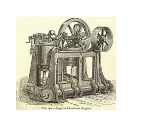
Brayton Cycle for Power Generation Natural Resource
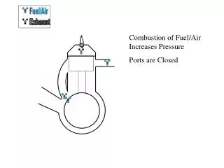
Combustors • Heat input (through Natural Resources) to the gas turbine Brayton cycle is provided by a combustor. • The combustor accepts air from the compressor and delivers it at an elevated temperature to the turbine. • A combustor is a direct fired air heater in which fuel is burned almost stoichiometrically. • The compressor discharges at least three times the stoichiometric air. • Only one third participates in combustion.
First Law Analysis of Furnace:SSSF • dm C.V. • = 0 • dt • dE C.V. • = 0 • dt • Conservation of Mass: • m comp. air + m fuel - mfluegas = 0 • First Laws for SG in SSSF Mode: • S m in (h + ½ V2+gZ) in = S m fluegas (h + ½ V2+gZ)fluegas • Temperature of flue gas will be very high. • Turbine materials cannot withstand such a high temperature. • More Dilution air is required. m fuel m fluegas m compressedair
Performance of Combustor • Combustor efficiency is a measure of combustion completeness.
The loss of pressure in combustor (p3 <p2) is a major problem. • The total pressure loss is usually in the range of 2 – 8% of p2. • The pressure loss leads to decrease in efficiency and power output. • This in turn affects the size and weight of the engine. • Combustion Terms • Reference Velocity: The theoretical velocity for flow of combustor inlet air through an area equal to the minimum cross section of the combustor casing. (20 – 40 m/s). • Profile Factor: The ratio between the maximum exit temperature and the average exit temperature.
Length Scaling • An estimate of the size of main burner is required during the engines preliminary design. • The cross sectional area can be easily determined using velocity constraints. • The length calculations require scaling laws. • The length of a main burner is primarily based on the distance required for combustion to come to near completion. • Residence time tres in main burner is given by
Combustion Design Considerations • Cross Sectional Area: The combustor cross section is determined by a reference velocity appropriate for the particular turbine. • Another basis for selecting a combustor cross section comes from thermal loading for unit cross section. • Length: Combustor length must be sufficient to provide for flame stabilization. • The typical value of the length – to – diameter ratio for liner ranges from three to six. • Ratios for casing ranges from two – to – four. • Wobbe Number: Wobbe number is an indicator of the characteristics and stability of the combustion process. • Pressure Drop: The minimum pressure drop is upto 4%. • Volumetric Heat Release Rate: The heat-release rate is proportional to combustion pressure. Actual space required for combustion varies with pressure to the 1.8 power.
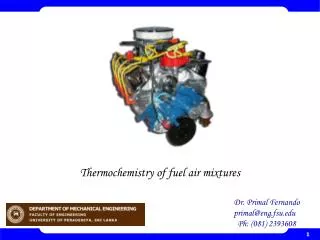
Modeling of Combustion • CXHYSZ +e 4.76 (X+Y/4+Z) AIR + Moisture in Air + Moisture in fuel → P CO2 +Q H2O +R SO2 + T N2 + U O2 + V CO • Exhaust gases: P CO2 +QH2O+R SO2 + T N2 + U O2 + V CO kmols. • Excess air coefficient : e. • Volume fraction = mole fraction. • Volume fraction of CO2 : x1 = P * 100 /(P+R+ T + U + V) • Volume fraction of CO : x2= VCO * 100 /(P +R+ T + U + V) • Volume fraction of SO2 : x3= R * 100 /(P +R+ T + U + V) • Volume fraction of O2 : x4= U * 100 /(P +R+ T + U + V) • Volume fraction of N2 : x5= T * 100 /(P +R+ T + U + V) • These are dry gas volume fractions. • Emission measurement devices indicate only Dry gas volume fractions.
Emission Standards • 15% oxygen is recommended in exhaust. • NOx upto 150 ppm. • SO2 upto 150 ppm. • CO upto 500 ppm. • HC upto 75 ppm. • Volume fractions of above are neglected for the calculation of specific heat flue gas.
For a given mass flow rate of fuel and air, the temperature of the exhaust can be calculated using above formula. If mass flow rates of fuel and air are known. Guess approximate value of specific heat of flue gas. Calculate T3. Calculate cp,flue gase. Re calculate T3. Repeat till the value of T3 is converged.
For an infinitesimal expansion from p+idp: Evaluation of Polytropic efficiency, hturb,.
Global Cycle Parameters Actual Power Input to Compressor: Rate of Heat Input in Combustion Chamber: Actual Power Output of Turbine: Net Power Output of Plant: