Download
1 / 22
220 likes | 379 Vues
Diesel Cycle and the Brayton Cycle. Chapter 9b. Rudolph Diesel. German inventor who is famous for the development of the diesel engine The diesel engine is based on a compression ignition system. http://www.autonews.com/files/euroauto/inductees/diesel.htm. Diesel Engines. No spark plug

E N D
Diesel Cycle and the Brayton Cycle Chapter 9b
Rudolph Diesel • German inventor who is famous for the development of the diesel engine • The diesel engine is based on a compression ignition system http://www.autonews.com/files/euroauto/inductees/diesel.htm
Diesel Engines • No spark plug • Fuel is sprayed into hot compressed air
Diesel Cycle Otto Cycle The only difference is in process 2-3
Consider Process 2-3 • This is the step where heat is transferred into the system • We model it as constant pressure instead of constant volume
Consider Process 4-1 • This is where heat is rejected • We model this as a constant v process • That means there is no boundary work
As for any heat engine… substitute
Rearrange rc is called the cutoff ratio – it’s the ratio of the cylinder volume before and after the combustion process
rc This doesn’t do us much good
rc Since Process 1-2 and Process 3-4 are both isentropic 1 1
Finally, Since process 1-2 is isentropic The volume ratio from 1 to 2 is the compression ratio, r
The efficiency of the Otto cycle is always higher than the Diesel cycle • Why use the Diesel cycle? • Because you can use higher compression ratios
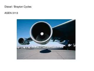
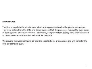
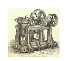
Brayton Cycle • Ideal Cycle for Gas Turbine Engines • Usually operate on an open cycle
Closed cycle model for a gas turbine engine 1-2 Isentropic Compression 2-3 Constant Pressure heat addition 3-4 Isentropic Expansion 4-1 Constant Pressure heat rejection
Closed cycle model for a gas turbine engine 4-1 Constant Pressure heat rejection 2-3 Constant Pressure heat addition 3-4 Isentropic Expansion 1-2 Isentropic Compression
Remainder of the Chapter • I’m not skipping the other sections in this chapter because they are unimportant, or uninteresting • We just don’t have time!!