Download
1 / 20
220 likes | 719 Vues
MERCURY CLEANUP THROUGH THE USE OF ELECTROCHEMICAL REMEDIATION TECHNOLOGIES. Expertise in Geology, Engineering and Environmental Science. Weiss Associates P2-Soil Remediation, Inc. Electro Petroleum Inc. presentation at “Breaking the Mercury Cycle” Conference Boston, Massachusetts

E N D
MERCURY CLEANUP THROUGH THE USE OF ELECTROCHEMICAL REMEDIATION TECHNOLOGIES Expertise in Geology, Engineering and Environmental Science Weiss Associates P2-Soil Remediation, Inc. Electro Petroleum Inc. presentation at “Breaking the Mercury Cycle” Conference Boston, Massachusetts May 1–3, 2002 prepared by Falk Doering, Ph.D., & Niels Doering—P2 Soil Remediation, Inc. Joe L. Iovenitti, Donald J. Hill, Ph.D., & William A. McIlvride—Weiss Associates J. Kenneth Wittle—ElectroPetroleum, Inc. Weiss Associates is skilled and experienced in areas essential to Environmental Industry geoscience problem solving. Staff membersinclude geologists; hydrogeologists; civil, environmental, chemical and mechanical engineers; environmental scientists; regulatory specialists and technicians. We recognize that each individual'sintelligence, creativity and perseverance are essential ingredients to create a superiorwork product. These individual human traits are cultivated and encouraged at WA. WA's staff uses the most advanced field equipment, techniques and computer technology. Quality is maintained through communication with staff and careful recruiting, training and supervision. The result is work that consistently satisfies or exceeds the require-ments of our clients and local, state and federal regulators. At Weiss Associates, outstanding people produce outstanding results. For additional information, please contact Joe L. Iovenitti Telephone (510) 450-6141 Fax (510) 547-5043 e-mail jli@weiss.com
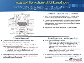
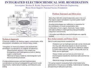
DIRECT CURRENT TECHNOLOGIES Direct Current Technologies (DCTs) ElectroChemical Remediation ElectroKinetics ElectroChemicalGeoOxidation (ECGO) Induced Complexation (IC) Geotechnical Applications Carbon Dioxide Vacuum Stripping Wells with Electrolytic Destruction (CVS-II) Electro-Kinetic Aided Remediation (EKAR)
INDUCED REDOX REACTIONS • How Do They Occur? • Electrodes are placed in the sediment where a low voltage and low amperage coupled DC/AC field is imposed • An Induced Polarization (IP) field is created • the soil acts as a capacitor, discharging and charging electricity • electrical discharge cycle causes reduction • electrical charging cycle causes oxidation • REDOX reactions occur at a high frequency throughout the matrix
INDUCED REDOX REACTIONS • Where Do They Occur? • In the soil under Ex-Situ or In-Situ conditions • Reactions take longer in gravel than fine sand, fine sand takes longer than clay • Reaction rate is inversely proportional to grain size • At the Pore Scale • Theory = Reactions occur at any and all interfaces within the soil-water-contaminant system No pumping or addition of chemicals required during ECRTs-ECGO or ECRTs-IC.
ECRTs PORE SCALE REDOX MODEL Sorbed water molecule Hydrated Anion Soil Particle or Colloid Hydrated Cation A zone of redox reaction Diffuse layer Outer Helmholtz Plane Inner Helmholtz Plane Hygroscopic Water— serves as a dielectric REDOX reactions occur at any and all interfaces and are believed to result from electrolysis of water. Capacitor Structure
UNION CANAL, SCOTLAND • Water TDS: ~ 3.5 g/l mainly sodium chloride • Main Pollutants: Elemental and methyl Hg • Electrodes: Steel pipes 192 mm OD, each 8 m long • Power input: 5.6 kW • Sediment: silts • Initial Average Total Hg Concentration: 243 mg\kg
UNION CANAL, SCOTLAND 220 m3
UNION CANAL, SCOTLAND Results (all figures in mg Hg/kg dm) • After 26 days of remediation 168 lbs of mostly mercury was deposited on both electrodes • Post-remediation average total Hg Concentration = 6 mg/kg; cleanup objective was 20 mg/kg
MONTLUÇON, FRANCE • . • 350 T of Sewage Treatment Plant Sludge Contaminated with Hg from Dental Amalgams • Pretreatment Hg Concentration = 15 mg\kg to 54 mg/kg; Cleanup Level = 5 mg/kg • Ex-Situ Treatment with 2.3 kW Power Input over 7 Days; Total Project Electrical Cost ~$40 @ $0.10 \ kW-hr • Final Hg concentrations = 0.02 to 0.35 mg/kg, Significantly Below the Cleanup Level
Y-12 PLANT, OAK RIDGE ECRTs Mercury Remediation Laboratory Test • Soil box: 90 cm x 50 cm x 45 cm with 150 L of saturated (fresh water) Y-12 contaminated clay loam • Plate electrodes: 80 cm x 32 cm • Initial Hg concentration: 252 mg/kg
Y-12 PLANT, OAK RIDGE ECRTs Laboratory Test • Typically ECRTs Can Not Be Tested in the Laboratory Due to the Electrical System Resistance • Y-12 Plant Soil Contains 12,000 mg\kg Iron Making It Highly Electrically Conductive Allowing the ECRTs-IC Phenomena to Occur • Evidence for the ECRTs-IC Phenomena Is Indicated by the Migration of Mercury to the Anode which Can Only Occur Through the Formation of Negative Hg Complexes • Hg concentration increase is >100% at anode • Hg concentration decrease is 60% at cathode
Y-12 PLANT, OAK RIDGE • Sampling after 81, 450, and 741 hrs of operation at sites between anode and cathode electrodes Approximate Plate Electrode Positions Sampling the Test Array • Sampling Locations at the Anode Face, Quarter Point, Mid-Point, Three Quarter Point, and Cathode Face
Y-12 PLANT, OAK RIDGE LABORATORY TEST RESULTS • Hg Contaminated Soils Saturated with Fresh Water Were Successfully Treated to below the DOE Site Imposed TCLP Cleanup Level • Mercury species reported by DOE Site to be present include: • mercury chloride, mercury nitrate, mercury sulfide, elemental mercury, and methyl mercury • No detailed Hg speciation conducted during test reported herein • Laboratory Results Corroborate Fresh and Brackish Water Field Remediation Results
Y-12 PLANT, OAK RIDGE ACKNOWLEDGEMENTS • Work conducted for the U.S. Department of Energy (DOE) National Environmental Technology Laboratory (NETL) in cooperation with DOE Oak Ridge Operations Office and Bechtel Jacobs, LLC, the DOE Oak Ridge environmental site contractor. • Work completed with assistance from TPG Applied Technology, ADA Technologies, Inc., and Hazen Research.
FUNDED ECRTs PROJECTS • PCBs in Soils/Sediment at an Upland Site, New York • Hg, Phenols, PCBs and PAH in Marine Sediments, Puget Sound, Washington (USEPA SITE Program Project) • Chlorinated Volatile Organic Compounds in Soil and Ground Water, NAS Dallas, Texas • PAHs in Lake Superior Fresh Water Sediments, Minnesota