Download

1 / 29
360 likes | 715 Vues
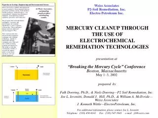
ESSEE 4. Palić, Serbia, 17 – 22 Sept., 2006. ELECTROCHEMICAL REMEDIATION. Achille De Battisti Laboratory of Elettrochemistry Department of Chemistry of the University of Ferrara. Targets: Non-destructive removal of pollutants from soils.

E N D
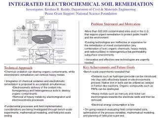
ESSEE 4 Palić, Serbia, 17 – 22 Sept., 2006 ELECTROCHEMICAL REMEDIATION Achille De Battisti Laboratory of Elettrochemistry Department of Chemistry of the University of Ferrara
Targets: Non-destructive removal of pollutants from soils - Detoxification/sterilization of industrial wastewaters, landfill leachates, swimming-pool water, water in food industry. - Cold incineration of organic wastes and disgregation of radioactive residuals. - Quality improvement of potable water, detoxification/sterilization of groundwaters
Soils: Electrochemical (electrokinetic) extraction of pollutants Methods: Imposition of potential gradients across the soil portion to be remediated polarizing suitably positioned electrodes Primary effects: displacement of charged species (electromigration, electro-osmosis), and neutral species (electro-osmosis). Secondary effects: Accumulation of pollutants in electrodic spaces, followed by abatement.
Soils: Electrochemical (electrokinetic) remediation Advantages:in situ methods, substantially non-destructive, no chemicals used, low energy consumption (e.g..: few tens of Volts and currents of the order of few Amperes); flexibility (e.g.: D.C. , A.C. polarization), Disadvantages: possible incompatibility with the specific features of the site to be reclamated, problems of stability for metallic structures in the soil.
Electrokinetic phenomena: some general aspects - - - - - - - - - - - - S + + + + + 2 + + + 0 Solution flow + + + + + Sharing plane Outer Helmholtz Plane
Further information on an electrified interfase interphase or = potential at the distance x from the charged wall 0= potentialat the charged wall 2=potential atthe OuterHelmholtz Plane (OHP) = permittivity of the liquid phase -1= diffuse-layer “thickness”
transit plane ve + + + + + + + + charge plane (qd) -1 - - - - - - - - - - - surface of the immobile solid with charge density -qd
Electrode Electro-osmotic flow Electrolyte solution Electrode Flow of electrolyte solutions through capillary channels with charged surface Elettro-osmosis Phenomenological equation Ve=electro-osmotic flow rate; P=pressure gradient; E=campo elettrico
Flow of electrolyte solutions through capillary channels with charged surface Streaming currents and potentials Electrode Electrokinetic current Electrolyte solution Electrode Phenomenological equation: j = current density; P=pressure gradient; E=electric field
- - - - - - - - - - - - - + + + + + + + + + + + + + + + + + + + + + + + + + + E - - - - - - - - - - - - - v Qualitative representation of the profile of the electro-osmotic flow rate in a capillary channel
- - + - + + + + + + - - + - + + - + + - - - - + - + - - - - + + - - - + + + + - - + + + - + + + - - + - - - - - + - + - - + + + - + - - - - + - - - + + + - + + + Simplified scheme of a particle plug with surface ionogenic groups: fixed solid-mobile solution Hydrostatic pressure gradients across the plug, cause a displacement of a fraction of the volume-charge in the direction of the fluid flow. As a consequence, streaming currents and potentials are measured
In the hypotesis that the shear plane and capillary surface cohincide: From former definitions and developments we have also:
Transport due to the electric field: electro-osmosis Ve = electro-osmotic flow rate ue = electro-osmotic velocity Ke = electro-osmotic permeability coefficient E = electric field A = total cross-sectional area
Some considerations on the electro-osmotic permeability coefficient The electro-osmotic permeability coefficient, ke is independent from the pore diameter, at variance with the hydraulic permeability coefficient, kh. The experimental values of ke do not depend on soil nature and change within a very narrow range, between 10-9 e 10-8 m2 V-1 s-1, while kh ranges between 10-13 e 10-5 m s-1. An electric gradient is more effective than an hydraulic one in fine-grained soils. Electro-osmotic flow is well controlled, being confined within the area across which electric field is active Being for a given soil negative, the electro-osmotic flow is addressed toward the cathode.
Transport under the effect of electric field: electromigration The dependence of ion elettromigration on potential gradient, in a capillary: Where vm is the ion velocity, is the ionic mobility, assuming values typically around 3.10-8 m2 v-1 s-1 (about one order of magnitude higher for H+ e OH- ) Electromigration is affected by electric field, and ionic strength.
Important factors in electrokinetic remediation Soil chemistry, or soil-contaminant interaction: The kinetics of the removal of contaminants is bound to adsorption phenomena, ion-exchange, buffering capacity Water content: inhomogeneous distribution of humidiy and consolidation may take place during an electrokinetic Soil structure: clogging of the soil porous texture and blocking of the electro-osmotic flow may take place due to hydroxide (presence of heavy metals). Positioning of the electrodes and electrode structure: Solidity of the structure, easy workability, chemical stability, costs, are major actors. graphite, activated Titanium are electrode materials of practical interest.
Optimization of the electro-osmotic process -use of “washing” liquids , like water, diluite NaCl solutions. -control of soil pH by means of buffering substances. -washing of electrodic compartments, by addition of water/water solutions. -addition of complexing agents, for heavy-metal removal -weak alkalinization and/or adition of surfactants for the removal of strongly adsorbed organic contaminants
Simple equipment for Studies in electrokinetic soil remediation
Electrode distribution (bench scale to commercial installations
Electrode distribution (bench scale to commercial installations
Electrokinetic soil remediation: time required/1 V = rate of species transport (or velocity: LT-1) i*= effective ionic mobility L2T-1V-1 Ke = coefficient of electroosmotic permeability L2T-1V-1 Rdc= delaying factor (dimensionless, depends on soil type, pH, and contaminant nature. Accounts for contaminant desorption and dissolution. E = the electric gradient V L-1
Electrokinetic soil remediation: time required/2 The remediation time TE required for a given contaminant in a soil may be expressed as: LE/v, where LE is the spacing between electrodes of opposite polarity σ* = effective soil conductivity (siemens m-1) β is a lumped property of the contaminant and of the soil (L3 C-1), similar to transference numbers in electrochemistry, but it also accounts for electroosmosis, soil conditions and retardation caused by geochemical reaction:
Electrokinetic soil remediation: time required/3 β is a fundamental parameter in electrokinetic soil remediation. Its values typically range within 1.10-9 and 1.10-6 m3 C-1 If the remediation time has to be calculated on the basis of current density applied across the soil, then we have: Where Id is the electric current density = I/A (amp L-2), I is the total current and A the cross-sectional area of the soil treated.
Veduta schematica dell’installazione di una PRB PERMEABLE REACTIVE BARRIERS Groundwater treatment • Definition andmethodology • PRB normal with respect to groundwater flow. • Containing reactive material Two types of installation Funnel-and-gate and continuous PRB
Encouraging number of commercial installations: the situation in USA
2Fe0 + O2 + 2 H2O 2 Fe2+ + 4 OH– Fe3+ + 3 OH–Fe(OH)3 (S) Aerobic environment Fe0+ 2H2O Fe2+ + H2 + 2OH– Fe2+ + 2OH–Fe(OH)2 (S) Anaerobic environment PERMEABLE REACTIVE BARRIERS Reductive degradation of organochloro componds with oxidation of Fe0 a Fe2+ Fe0 + RCl + H+ Fe2+ + RH + Cl- important!! Hydraulic permeability and reactivity of the barrier
O2 cathodic reduction in presence of Fe2+ Further oxidation ANODE CATHODE from PRB to Electrochemical Reactor Possible efficiency problem: Barrier aging and degradation Electrochemically generated Fenton reactant Fe²++ H2O2 Fe³+ + .OH + OH- Fe³+ + H2O2 Fe²+ + .OOH + H+ Reazione di Fenton Oxidative attack to organic substrates
Hybrid Processes - Synergism has been observed in the application of electric fields and hydraulic pressure gradients (removal of heavy metals from da mixtures sand/process-sludge -Similar observations in the use of acoustic treatments coupled with the electro-osmotic one (removal of decane, Zn, Cd, from clays) -Electrodialysis: The efficiency of removal of heavy metals and maintenance of treated soil pH can be improved making use of ion-exchange membranes. -Bioremediation: The displacement of nutrients and colonies of microorganisms under the action of electric fields may favour the removal of complex organic species. -Fitoremediation: the transfer of the pollutant to the treated area accelerates the removal process.
Suggested reference: I.K. Iskander, Environmental Restoration of Metals-Contaminated Soils Lewis Publ., London, 2001