Download

1 / 63
640 likes | 1.01k Vues
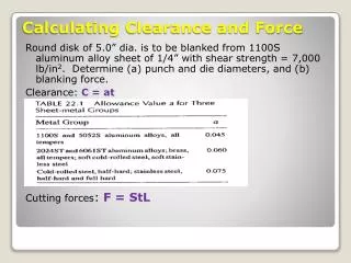
Round disk of 5.0” dia. is to be blanked from 1100S aluminum alloy sheet of 1/4” with shear strength = 7,000 lb/in 2 . Determine (a) punch and die diameters, and (b) blanking force. Clearance: C = at Cutting forces : F = StL. Calculating Clearance and Force.

E N D
Round disk of 5.0” dia. is to be blanked from 1100S aluminum alloy sheet of 1/4” with shear strength = 7,000 lb/in2. Determine (a) punch and die diameters, and (b) blanking force. Clearance: C = at Cutting forces: F = StL Calculating Clearance and Force
Calculation for Sheet-metal Bending Metal to be bent with a modulus of elasticity E = 30x106 lb/in2., yield strength Y = 40,000lb/in2 , and tensile strength TS = 65,000 lb/in2. Determine (a) starting blank size, and (b) bending force if V-die will be used with a die opening dimension D = 1.0in. (a) Bending Allowance: BA = 2pA(R + Kbat)/360 Kba - factor to estimate stretching. If R < 2t, Kba = 0.33; and if R>=2t, Kba =0.5. (b) Bending force: F = (KbfTSwt2)/D Kbf – a constant that counts for differences in an actual bending processes. For V-bending Kbf =1.33, and for edge bending Kbf =0.33
Chapter 17Sheet Forming Processes(Part 2)Drawing & Stretching, Alternative Methods, Pipe Welding, and PressesEIN 3390 Manufacturing ProcessesSpring 2012
Drawing refers to the family of operations where plastic flow occurs over a curved axis and the flat sheet is formed into a three-dimensional part with a depthmore than several times the thickness of the metal • Application: a wide range of shapes, from cups to large automobile and aerospace panels. 17.4 Drawing and Stretching Processes
Types of Drawing and Stretching • Spinning • Shear forming or flow turning • Stretch forming • Deep drawing and shallow drawing • Rubber-tool forming • Sheet hydroforming • Tube hydroforming • Hot drawing • High-energy-rate forming • Ironing • Embossing • Superplastic sheet forming 17.4 Drawing and Stretching Processes
Spinning is a cold forming operation • Sheet metal is rotated and progressively shaped over a male form, or mandrel • Produces rotationally symmetrical shapes • Cones, spheres, hemispheres, cylinders, bells, and parabolas 17.4 Spinning
Figure 17-34 (Above) Progressive stages in the spinning of a sheet metal product. Spinning
Figure 17-35 (Left) Two stages in the spinning of a metal reflector. (Courtesy of Spincraft, Inc. New Berlin, WI.) Spinning
Tooling cost can be extremely low. The form block can often be made of hardwood or even plastic because of localized compression from metal. With automation, spinning can also be used to mass-produce high-volume items such as lamp reflectors, cooking utensils, bowls, and bells. Spinning is usually considered for simple shapes that can be directly withdrawn from a one-piece form. More complex shapes, such as those with reentrant angles, can be spun over multipiece or offset forms. Spinning
Shear forming is a version of spinning • A modification of the spinning process in which each element of the blank maintains its distance from the axis of rotation. • No circumferential shrinkage • Wall thickness of product, tc will vary with the angle of the particular region: tc = tb(sin a) where tb is the thickness of the starting blank. • Reductions in wall thickness as high as 8:1 are possible, but the limit is usually set at about 5:1, or 80% Shear Forming
Material being formed moves in the same direction as the roller Figure 17-36 Schematic representation of the basic shear-forming process. Direct Shear Forming
Material being formed moves in the opposite direction as the roller • By controlling the position and feed of the forming roller, the reverse process can be used to shape con- cave, convex, or conical parts without a matching form block. Reverse Shear Forming
An attractive means of producing large sheet metal parts in low or limited quantities. A sheet of metal is gripped by two or more sets of jaws with stretching or wrapping around a single form block. Stretch Forming Figure 17-39 Schematic of a stretch-forming operation.
Most deformation is induced by the tensile stretching, so the forces on the form block are far less than those encouraged in bending or forming. Very little springbackand the workpiece conforms very closed to the shape of the tool. Wrinkles are pulled out before they occur since stretching accompanies bending or wrapping Stretch Forming
Form blocks can be made of wood, low-melting-point metal, or even plastic because forces on form block are low. Quite popular in the aircraft industry to form aluminum, stainless steel into cowling, wing tip, scoop, and other large panels. Low-carbon steel can be stretched to produce large panels for automotive and truck industry. If mating male and female dies are used to shape the metal while it is being stretched, the process is known as stretch-draw forming. Stretch Forming
Deep Drawing and Shallow Drawing • Drawingis typically used to form solid-bottom cylindrical or rectangular containers from sheet metal. • When depth of the product is greater than its diameter, it is known “Deep drawing”. • When depth of the product is less than its diameter, it is known “shallow drawing”. Figure 17-40 Schematic of the deep-drawing process.
Deep Drawing and Shallow Drawing • Key variables: • Blank and punch diameter • Punch and die radius • Clearance • Thickness of the blank • Lubrication • Hold-down pressure Figure 17-4 Flow of material during deep drawing. Note the circumferential compression as the radius is pulled inward
During drawing, the material is pulled inward, so its circumference decrease. Since the volume of material must be the same, V0 = Vf the decrease in circumferential dimension must be compensated by a increase in another dimension, such as thickness or radial length. Since the material is thin, an alternative is to relieve the circumferential compression by bulking or wrinkling. The wrinkling formation can be suppressed by compressing the sheet between die and blankholder service. Deep Drawing and Shallow Drawing
The hold-down force is independent of the punch position. The restraining force can be varied during the drawing operation. Multi-action presses are usually specified for the drawing of more complex parts. Deep Drawing and Shallow Drawing Figure 17-42 Drawing on a double-action press, where blankholder uses the second press action
Once a drawing process has been designed and the tooling manufactured, the primary variable for process adjustment is hold-down pressure or blankhoder force. If the force is too low, wrinkling may occur at the start of the stroke. If it is too high, there is too much restrain, and the descending punch will tear the disk or some portion of the already-formed cup wall. Deep Drawing and Shallow Drawing
As cup depth increases or material is thin, there is an increased tendency for forming the defects. Thin Thick Deep Drawing
Wrinkling and tearing are typical limits to drawing operations • Trimming may be used to reach final dimensions Limitations of Deep Drawing Figure 17-45 Pierced blanked, and drawn part before and after trimming
Blanking and drawing operations usually require mating male and female die sets • Processes have been developed that seek to • Reduce tooling cost • Decrease setup time and expense • Extend the amount of deformation for a single set of tools Forming with Rubber Tooling or Fluid Pressure
Alternative Forming Operations • Several forming operations replace one of the dies with rubber or fluid pressure • Guerin process • Other forming operations use fluid or rubber to transmit the pressure required to expand a metal blank • Bulging Figure 17-47 Method of blanking sheet metal using the Guerin process. Figure 17-48 Method of bulging tubes with rubber tooling.
Guerin process was developed by aircraft industry for small number of duplicate parts. The sheet materials can be aluminum up to (1/8”) thick and stainless steel up to 1/16”. Magnesium sheet can also be formed if it is heated and shaped over heated form block. Guerin Process (Rubber-die forming)
Sheet Hydroforming • Sheet hydroforming is a family of processes in which a rubber bladder backed by fluid pressure replaces either the solid punch or female die set • Advantages • Reduced cost of tooling • Deeper parts can be formed without fracture • Excellent surface finish • Accurate part dimensions
Sheet Hydroforming Figure 17-50 (Above) One form of sheet hydroforming. Figure 17-51 Two-sheet hydroforming, or pillow forming.
Tube Hydroforming • Process for manufacturing strong, lightweight, tubular components • Frequently used process for automotive industry • Advantages • Lightweight, high-strength materials • Designs with varying thickness or varying cross section can be made • Welded assemblies can be replaced by one-piece components • Disadvantages • Long cycle time • Relatively high tooling cost and process setup Figure 17-52 Tube hydroforming. (a) Process schematic.
Hot-drawing • Sheet metal has a large surface area and small thickness, so it cools rapidly • Most sheet forming is done at mildly elevated temperatures • High-Energy Rate Forming (HERF) • Large amounts of energy in a very short time • Underwater explosions, underwater spark discharge, pneumatic-mechanical means, internal combustion of gaseous mixtures, rapidly formed magnetic fields • Ironing • Process that thins the walls of a drawn cylinder by passing it between a punch and a die Additional Drawing Operations
Hot-Drawing Processes Figure 17-5 Methods of hot drawing a cup-shaped part. (Up left) First draw. (Up right) Redraw operation. (Lower) Multi-die draw. (Courtesy of United States Steel Corp., Pittsburgh, PA)
Embossing • Pressworking process in which raised lettering or other designs are impressed in sheet material • Superplastic sheet forming • Materials that can elongate in the range of 2000 to 3000% can be used to form large, complex-shaped parts with ultra-fine grain size and performing the deformation at low strain rates and elevated temperature. • Superplastic forming techniques are similar to that of thermoplastics Additional Drawing Operations
Tensile strength of the material is important in determining which forming operations are appropriate. • Sheet metal is often anisotropic- properties vary with direction or orientation. A metal with low-yield, high-tensile, and high-uniform elongation has a good mechanical property for sheet-forming operations. • Majority of failures during forming occur due to thinning or fracture • Strain analysis can be used to determine the best orientation for forming Properties of Sheet Material
It is important to assess the limitation of the amount of drawing that can be accomplished. • Measures of Drawing: • 1) Drawing ratio (cylinder) DR = Db/Dp • Where Db – blank diameter, Dp – punch diameter • The greater the ratio, the more severe is the drawing. • An approximate upper limit on the drawing ratio is a value of 2.0. The actual limiting value for a given drawing depends on punch and die corner radii (DpandDd), friction conditions, depth of draw, and characteristics of the sheet metal (ductility, degree of directinality of strength in the metal). Engineering Analysis of Drawing
2) Reduction r (another way to characterize a given drawing) r = (Db -Dp)/Db It is very closely related to drawing ratio. Consistent with Dr <= 2.0, the value of r should be less than 0.5. 3) Thickness-to-diameter ratio: t/Db Where t – thickness of the starting blank, Db – blank diameter. The ratio t/Db is greater than 1%. As t/Db decreases, tendency for wrinkling increases. If DR , r, t/Db are exceeded by the design, blank must be draw in two or more steps, sometimes with annealing between steps. Engineering Analysis of Drawing
Example: Cup Drawing For a cylindrical cup with inside diameter = 3.0” and height = 2.0”, its starting blank size Db = 5.5”, and its thickness t = 3/32”, please indicate its manufacturing feasibility. Solution: DR = Db/Dp = 5.5/3.0 = 1.833 <2.0 r = (Db -Dp)/Db = (5.5 – 3.0)/5.5 = 45.45% < 50% t/Db = (3/32)/5.5 = 0.017 > 1% So the drawing operation is feasible. Engineering Analysis of Drawing
Drawing Force F = pDpt(TS)(Db/Dp – 0.7) Where F – drawing force, lb(N); t – thickness of blank, in. (mm); TS - tensile strength, ib/in2 (Mpa); Db and D p – starting blank diameter and punch diameter, in. (mm). 0.7 – a correction factor for friction. The equation is the estimation of the maximum force in the drawing. The drawing force varies throughout the downward movement of the punch, usually reaching its maximum value at about one-third the length of the punch stroke. Clearance c: about 10% than the stock thickness (t) c = 1.1 t Engineering Analysis of Drawing
Holding Force Fh = 0.015Yp[Db2 – (Dp + 2.2t + 2Rd)2] Where Fh– holding force in drawing, ib (N); Y – yield strength of the sheet metal, lb/in2 (Mpa); t – starting stock thickness, in. (mm); Rd – die conner radius, in. (mm). The holding force is usually about one-third the drawing force [1]. [1]: Wick, C., et al., “Tool and Manufacturing Engineers, 4th ed. Vol. II. Engineering Analysis of Drawing
Example Forces in Drawing Determine the (a) drawing force, and (2) holding force for the case in previous example for feasibility, where tensile strength of the metal = 70,000 lb/in 2 and yield strength = 40,000 lb/in 2 , the die corner radius = 0.25”. Solution: (a) F = pDpt(TS)(Db/Dp – 0.7) =p(3.0)(3/32)(70,000)(5.5/3.0 – 0.7) =70,097 lb (b) Fh = 0.015Yp[Db2 – (Dp + 2.2t + 2Rd)2] = 0.015(40,000)p{5.52 – [3.0 + 2.2(3/32) + 2(0.25)]2} = 1,885 (30.25 – 13.74) = 31,121 lb Engineering Analysis of Drawing
Blank Size Determination Assume that the volume of the final product is the same as the that of the starting sheet-metal blank and the thinning of the part wall is negligible. For a cup with its height H and the same diameters Dpin the bottom and top: pDb2/4 = pDp2/4 + pDpH, and Db = SQRT(Dp2 + 4DpH) Engineering Analysis of Drawing
Design Aids for Sheet Metal Forming Figure 17-57 (Left) Typical pattern for sheet metal deformation analysis; (right) forming limit diagram used to determine whether a metal can be shaped without risk of fracture. Fracture is expected when strains fall above the lines.
A pattern is placed on the surface of a sheet. Circles have diameters between 2.4 and 5 mm (0.1 – 0.2”). During deformation, the circles convert into ellipses. Regions where the enclosed area has expanded are locations of sheet thinning and possible failure. Regions where the area has contracted have undergone sheet thickening and may be sites of buckling or wrinkles. Design Aids for Sheet Metal Forming