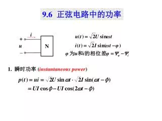
The instantaneous power
660 likes | 1.23k Vues
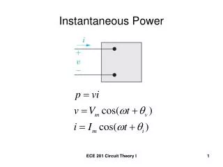
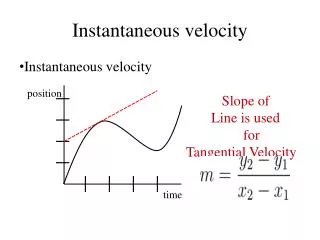
The instantaneous power. real (or average) power ( Watts ). Which is the actual power absorb by the element. Examples Electric Heater , Electric Stove , oven Toasters, Iron …etc. reactive power. Which is the reactive power absorb or deliver by the element.

The instantaneous power
E N D
Presentation Transcript
The instantaneous power real (or average) power (Watts) Which is the actual power absorb by the element Examples Electric Heater , Electric Stove , oven Toasters, Iron …etc reactive power Which is the reactive power absorb or deliver by the element Reactive power represents energy stored in reactive elements (inductors and capacitors). Its unit is Volt Ampere Reactive (VAR)
The instantaneous power real (or average) power (Watts) reactive power (Volt Ampere Reactive (VAR) )
Complex Power Previously, we found it convenient to introduce sinusoidal voltage and current in terms of the complex number the phasor Definition Let the complex power be the complex sum of real power and reactive power
Advantages of using complex power - We can compute the average and reactive power from the complex power S - complex power provide a geometric interpretation were The geometric relations for a right triangle mean the four power triangle dimensions ( , P, Q, ) can be determined if any two of the four are known
Power Calculations were Is the conjugate of the current phasor Circuit
In any circuit, conservation of complex power is achieved This implies that in any circuit, conservation of average power and Conservation of reactive power are achieved However, the apparent power (the magnitude of the complex power) is not conserved
Ex:6.13 Determine the average and reactive power delivered by the source. The phasor current leaving the source is The average power delivered by the source is:
The reactive power delivered by the source is: And the complex power delivered by the source is
Determine the average power and reactive power delivered to each element The voltage across the elements are: Thus the complex power delivered to each element is
show that conservation of complex power, average power, and reactive power is achieved.
6.6.1 Power Relations for the Resistor The voltage and current are in phase so Average power is: Reactive power is zero for resistor
6.6.1 Power Relations for the Inductor The voltage leads the current by 90 so that
6.6.1 Power Relations for the Capacitor The current leads the voltage by 90 so that
The power factor Recall the Instantaneouspower p(t) The angle qv - qi plays a role in the computation of both average and reactive power The angle qv - qi is referred to as the power factor angle We now define the following : The power factor
The power factor Knowing the power factor pf does not tell you the power factor angle , because To completely describe this angle, we use the descriptive phrases lagging power factor and leading power factor Lagging power factor implies that currentlagsvoltage hence an inductive load Leading power factor implies that currentleadsvoltage hence a capacitive load
6.6.2 Power Factor Since
EX:6.15 Determine the average and reactive powers delivered to the load impedance and the power factor of the load Average power
EX:6.15 Determine the average and reactive powers delivered to the load impedance and the power factor of the load OR
EX:6.15 Determine the average and reactive powers delivered to the load impedance and the power factor of the load OR
This could also be calculated from the complex power delivered to the load The power factor of the load is: The load is lagging because the current lags the voltage
A typical power distribution circuit The consumer is charged for the average power consumed by the load The load requires a certain total apparent power
Ex 6.16 Suppose that the load voltage figure is 170V The line resistance is 0.1 ohm The load requires 10KW of average power. Examine the line losses for a load power factor of unity and for a power factor of 0.7lagging. The load current is obtained from For unity power factor this is For power factor of 0.7 The powers consumed in the line losses 720 W extra power to be generated if pf is 0.7 to supply the load
Power Factor Correction Ex: 6.17: in Ex 6.16 determine the value of capacitor across the load to correct the power factor to unity if power frequency is 60Hz. (Negative because lagging) The angle of the current is: Thus the current into the load is: The current through the added capacitor is: Hence the total current Solving this to cancel out the reactive component gives: C=120.02/(2*3.14*60*170)=0.001873F
Power Factor Correction Ex: 6.17: in Ex 6.16 determine the value of capacitor across the load to correct the power factor from 0.7 to unity if power frequency is 60Hz. From Ex 6.16 For power factor of 0.7 power factor 0.7 lagging The current through the added capacitor is: Hence the total current Unity power factor Imaginary component of the line current is zero
6.6.3 Maximum Power Transfer Source-load Configuration Determine the load impedance so that maximum average power is delivered to that load. Represent the source and the load impedances with real and imaginary parts: The load current is:
The average power delivered to the load is: Since the reactance can be negative and to max value, we choose leaving Differentiate with respect to RL and set to zero to determine required RL which is RL= RS Hence: In this case the load is matched to the source. The max power delivered to the load becomes:
6.6.4 Superposition of Average Power Average power computation when circuit contains more than one source
The instantaneous power delivered to the element is Substituting Using the identity
Average powers delivered individually by the sources Suppose that the two frequencies are integer multiples of some frequency as The instantaneous power becomes
Averaging the instantaneous over the common period THUS: we may superimpose the average powers delivered by sources of different frequencies, but we may not, in general, apply superposition to average power if the sources are of the same frequency. where
Ex 6.18: Determine the average power delivered by the two sources of the circuit Hence the average power delivered by the voltage source is This can be confirmed from average powers delivered to the two resistors
By current division: The voltage across the current source is Hence the average power delivered by the current source is This may be again confirmed by computing the average power delivered to the Two resistors: Since frequencies are not the same, total average power delivered is the sum of average powers delivered individually by each source
EX 6.19: Determine the average power delivered by the two sources Since both sources have the same frequency, we can’t use superposition. So we include both sources in one phasor circuit. The total average power delivered by the sources is equal to the average power delivered to the resistor We use superposition on the phasor circuit to find the current across the resistor
The phasor current is: Hence the average power delivered to the resistor is Note that we may not superimpose average powers delivered to the resistors by the individual sources We can compute this total average power by directly computing the average power delivered by the sources from the phasor circuit The voltage across the current source is The average power delivered by voltage source is The average power delivered by the current source is The total average power delivered by the sources is
6.6.5 Effective (RMS) Values of Periodic Waveforms Sinusoidal waveform is one of more general periodic waveforms Apply a periodic current source with period T on resistor R The instantaneous power delivered to the resistor is The average power delivered to the resistor is Hence the average power delivered to the resistor by this periodic waveform can be viewed as equivalent to that produced by a DC waveform whose value is This is called the effective value of the waveform or the root-mean-square RMS value of the waveform
Ex 6.20 Determine the RMS value of the current waveform and the average power this would deliver to resistor The RMS value of the waveform is Hence the average power delivered to the resistor is
RMS voltages and currents in phasor circuits The sinusoid has a RMS value of Hence the average power delivered to a resistor by a sinusoidal voltage or current waveform is In general, the average power delivered to an element is Therefore, if sinusoidal voltages and currents are specified in their RMS values rather than their peak values, the factor ½ is removed from all average-power expressions. However, the time-domain expressions require a magnitude multiplied by square root of 2 Since X is the peak value of the waveform. Common household voltage are specified as 120V. This is the RMS value of the peak of 170V.
Ex 6.21 Determine the average power delivered by the source and the time-domain current i(t) Phasor circuit with rms rather than peak The phasor current is Hence the average power delivered by the source is The time-domain current is