AC Mitigation Overview - TGA
AC Mitigation Overview - TGA. High Voltage AC (HVAC) Power Lines Operating near Pipelines. November 15, 2013 Ryan Dillender. HVAC Power Lines and Pipelines. High voltage a lternating c urrent (HVAC) power lines operating near pipelines can be hazardous in two ways.

AC Mitigation Overview - TGA
E N D
Presentation Transcript
AC Mitigation Overview - TGA High Voltage AC (HVAC) Power Lines Operating near Pipelines November 15, 2013 Ryan Dillender
HVAC Power Lines and Pipelines • High voltage alternating current (HVAC) power lines operating near pipelines can be hazardous in two ways. • Electric shock hazards to people and animals. • Increased corrosion of metallic pipelines.
What is a HVAC Power Line? • High voltage alternating current (HVAC) power lines are grouped into transmission and distribution categories. • Typically lines of 26kV and less do not significantly impact pipelines, however severe phase imbalances can create abnormal issues.
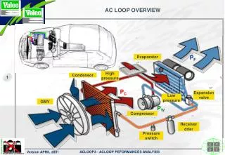
Influencing Factors • Typical HVAC transmission power lines are 138 kV, 230 kV, and 345 kV. • Typical HVAC transmission lines have historically had design limits in the 1000-3000 A range. • Conductor improvements now allow design limits of 5000 A. • Increased emphasis on sharing a common corridor has increased collocation length and frequency. • Increased HVAC power line construction activity. • Increased awareness in the industry of the AC related hazards and pipeline integrity.
Discovery of AC Interference Issue • Observation of new HVAC power line construction or increased awareness of existing issue. • Request of HVAC power line crossing. • Observation of unacceptable AC potential readings. • Must be taken at peak power line load. • Must be taken at proper location. • Observation of unacceptable AC density. • Must be taken at peak power line load and proper location. • Requires coupon test station.
AC Mitigation Project Lifecycle • Survey site and collect data • GPS data of location for pipelines and power lines • Resistances between power line structures and pipeline • Soil resistivity • Pipe to soil measurements • Pipeline parameters and alignment sheets • Power line parameters and plan and profile drawings. • Use computer model with collected data to predict impact of the HVAC power lines on the pipeline and design AC mitigation system. • AC potential (step and touch hazard) • AC density (corrosion hazard) • Install coupon test stations and AC mitigation system.
AC Mitigation – Criteria • AC Potential • Used to assess risk of step and touch safety hazard • 15 VAC or more is a shock hazard • NACE SP0177-2007 • AC Density • Used to assess risk of corrosion hazard • 20 A/m2or more is at risk for accelerated corrosion • NACE AC Corrosion State-of-the-Art, Publication 35110
AC Mitigation – Study Expectations • The AC interference study will typically identify the expected pipeline conditions under peak power line loading. • Field measurements are likely to be less than the expected peak values, unless field measurement are taken at peak power line loading.
AC Mitigation– Study Expectations T A TK TK1 Pipeline Power Line
AC Mitigation – Data Collection • The power grid is managed in real time without the use of stored energy. • There is no current limiting device on the power grid. • Load is balanced with lines being switched in and out of service. • HVAC transmission lines loads vary with time. • This variation can be driven by supply and/or demand. • Power lines often have an emergency rating. • This rating can be used for a short duration. • Conductor sag and melting is the limiting factor.
AC Interference – Mitigation Methods • AC interference is monitored using coupon test stations. • To be effective, test station must be monitored continuously. • Step and touch hazards can be mitigated with through the use of gradient mats and bonding. • The typical implementation of this is only effective at piping and appurtenances that are normally above ground. • Step and touch hazards as well as corrosion hazards can be mitigated through the use of grounding systems.
AC Mitigation – Grounding System • Grounding systems can mitigate AC interference along the entire length of the pipeline. • Grounding systems reduce the AC interferenceon the pipeline to acceptable levels. • Grounding systems are typically created by installing a grounded conductor that parallels the pipeline. • This is often accomplished with zinc ribbon. • In order to maintain adequate cathodic protection, a decoupling device is required.
AC Mitigation – Grounding System • Grounding systems are developed using survey and model data. • Grounding systems will be designed using a target pipeline to ground resistance value. • In general, the resistance of the pipe to ground circuit is lowered by increasing the surface area of the grounding material. • Horizontal and vertical lengths • Zinc and copper are both common grounding materials. • The use of copper requires close monitoring to ensure that it does not become connected to the pipeline in a way that allows DC to flow.
AC Mitigation – Decoupling Devices • The decoupling device allows AC to pass but not DC. • Types of devices • Polarization Cell (Kirk Cell) • Solid State Decoupler (SSD) • Polarization Cell Replacement (PCR) • Failure mode • Wet cells such as the Kirk Cell fail open. • Dry cells such as the SSD and PCR fail closed.
AC Mitigation – Operations Impact • Installation of grounding systems. • Installation of coupon test stations. • Increased remote monitoring. • Increased personal protective equipment (PPE). • Increased review of crossing agreements for potential AC interference issues. • Increased awareness of new HVAC power line construction. • If available, increased coordination with power companies to minimize expenditure and risks.
AC Interference – Code Requirements • Subpart G – General Construction Requirements for Transmission Lines and Mains • §192.328 – Additional construction requirements for steel pipe using alternative maximum allowable operating pressure • For a new or existing pipeline segment to be eligible for operation at the alternative maximum allowable operating pressure calculated under § 192.620, a segment must meet the following additional construction requirements…
AC Interference – Code Requirements • Subpart I – Requirements for Corrosion Control • § 192.473 – External corrosion control: Interference currents • (a) Each operator whose pipeline system is subjected to stray currents shall have in effect a continuing program to minimize the detrimental effects of such currents… • § 192.467 – External corrosion control: Electrical isolation. • … • (f) Where a pipeline is located in close proximity to electrical transmission tower footings, ground cables or counterpoise, or in other areas where fault currents or unusual risk of lightning may be anticipated, it must be provided with protection against damage due to fault currents or lightning, and protective measures must also be taken at insulating devices.
AC Interference – Code Requirements Subpart L – Operations § 192.620 – Alternative maximum allowable operating pressure for certain steel pipelines. …(d) What additional operation and maintenance requirements apply to operation at the alternative maximum allowable operating pressure? In addition to compliance with other applicable safety standards in this part, if an operator establishes a maximum allowable operating pressure for a pipeline segment under paragraph (a) of this section, an operator must comply with the additional operation and maintenance requirements as follows:
AC Interference – Code Requirements Subpart L – Operations § 192.620 – Alternative maximum allowable operating pressure for certain steel pipelines.
EN 15280:2013 – Current Density • Section 7 – Acceptable Interference LevelsThe design, installation and maintenance of the cathodic protection system shall ensure that the levels of a.c. voltage do not cause a.c. corrosion. Since the conditions vary for each situation, a single threshold value cannot be applied. • This is achieved by reducing the a.c. voltage on the pipeline and current densities as below: • As a first step, the a.c. voltage on the pipeline should be decreased to a target value, which should be 15 V rms or less. This value is measured as an average over a representative period of time (e.g. 24 h). and • As a second step, effective a.c. corrosion mitigation can be achieved by complying with criteria defined in EN 12954:2001, Table 1, and • maintaining the a.c. current density (rms) over a representative period of time (e.g. 24 h) to be lower than 30 A/m2 on a 1 cm2 coupon or probe; or • maintaining the average cathodic current density over a representative period of time (e.g. 24 h) lower than 1 A/m2 on a 1 cm2 coupon or probe if a.c. current density (rms) is more than 30 A/m2; or • maintaining the ratio between a.c. current density (Ja.c.) and d.c. current density (Jd.c.) less than 5 over a representative period of time (e.g. 24 h). • NOTE Current density ratios between 3 and 5 indicate a small risk of a.c. corrosion. However, in order to reduce the corrosion risk to a minimum value, smaller ratios of current density than 3 would be preferable … • Effective a.c. corrosion mitigation can be also demonstrated by measurement of corrosion rate.
HVAC Collocation in Texas Natural Gas Pipelines within 1 Mile of HVAC Power Lines
References • Page 3 • Image [http://www.ferc.gov/industries/electric/indus-act/reliability/blackout/ch1-3.pdf] • Page 4 • Image [By Dave Bryant (Own work) [CC-BY-SA-3.0 (http://creativecommons.org/licenses/by-sa/3.0)], via Wikimedia Commons] • Page 18 • Image [http://www.kirkcell.com/products-kirkcell.html]