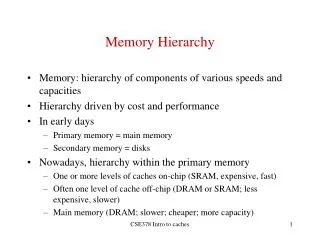
Appendix B. Memory Hierarchy
Appendix B. Memory Hierarchy. CSCI/ EENG – 641 - W01 Computer Architecture 1 Dr. Babak Beheshti. Slides based on the PowerPoint Presentations created by David Patterson as part of the Instructor Resources for the textbook by Hennessy & Patterson. Outline. Memory hierarchy Locality

Appendix B. Memory Hierarchy
E N D
Presentation Transcript
Appendix B. Memory Hierarchy CSCI/ EENG – 641 - W01 Computer Architecture 1 Dr. Babak Beheshti Slides based on the PowerPoint Presentations created by David Patterson as part of the Instructor Resources for the textbook by Hennessy & Patterson
Outline • Memory hierarchy • Locality • Cache design • Virtual address spaces • Page table layout • TLB (Translation Lookaside Buffers) design options
Gap grew 50% per year Since 1980, CPU has outpaced DRAM... Q. How do architects address this gap? A. Put smaller, faster “cache” memories between CPU and DRAM. Create a “memory hierarchy”. Performance (1/latency) CPU 60% per yr 2X in 1.5 yrs 1000 CPU 100 DRAM 9% per yr 2X in 10 yrs 10 DRAM 1980 1990 2000 Year
Apple ][ (1977) CPU: 1000 ns DRAM: 400 ns Steve Wozniak Steve Jobs 1977: DRAM faster than microprocessors
Levels of the Memory Hierarchy Upper Level Capacity Access Time Cost Staging Xfer Unit faster CPU Registers 100s Bytes <10s ns Registers prog./compiler 1-8 bytes Instr. Operands Cache K Bytes 10-100 ns 1-0.1 cents/bit Cache cache cntl 8-128 bytes Blocks Main Memory M Bytes 200ns- 500ns $.0001-.00001 cents /bit Memory OS 512-4K bytes Pages Disk G Bytes, 10 ms (10,000,000 ns) 10 - 10 cents/bit Disk -6 -5 user/operator Mbytes Files Larger Tape infinite sec-min 10 Tape Lower Level -8
Managed by compiler Managed by OS, hardware, application Managed by hardware iMac G5 1.6 GHz Memory Hierarchy: Apple iMac G5 Goal: Illusion of large, fast, cheap memory Let programs address a memory space that scales to the disk size, at a speed that is usually as fast as register access
L1 (64K Instruction) Registers 512K L2 (1K) L1 (32K Data) iMac’s PowerPC 970: All caches on-chip
Outline • Memory hierarchy • Locality • Cache design • Virtual address spaces • Page table layout • TLB (Translation LookasideBuffers) design options
The Principle of Locality • The Principle of Locality: • Program access a relatively small portion of the address space at any instant of time. • Two Different Types of Locality: • Temporal Locality (Locality in Time): If an item is referenced, it will tend to be referenced again soon (e.g., loops, reuse) • Spatial Locality (Locality in Space): If an item is referenced, items whose addresses are close by tend to be referenced soon (e.g., straightline code, array access) • Last 15 years, HW relied on locality for speed It is a property of programs which is exploited in machine design.
Bad locality behavior Temporal Locality Spatial Locality Programs with locality cache well ... Memory Address (one dot per access) Time Donald J. Hatfield, Jeanette Gerald: Program Restructuring for Virtual Memory. IBM Systems Journal 10(3): 168-192 (1971)
Outline • Memory hierarchy • Locality • Cache design • Virtual address spaces • Page table layout • TLB (Translation LookasideBuffers) design options
Lower Level Memory Upper Level Memory To Processor Blk X From Processor Blk Y Memory Hierarchy: Terminology • Hit: data appears in some block in the upper level (example: Block X) • Hit Rate: the fraction of memory access found in the upper level • Hit Time: Time to access the upper level which consists of RAM access time + Time to determine hit/miss • Miss: data needs to be retrieve from a block in the lower level (Block Y) • Miss Rate = 1 - (Hit Rate) • Miss Penalty: Time to replace a block in the upper level + Time to deliver the block the processor • Hit Time << Miss Penalty (500 instructions on 21264!)
Cache Measures • Hit rate: fraction found in that level • So high that usually talk about Miss rate • Miss rate fallacy: as MIPS to CPU performance, miss rate to average memory access time in memory • Average memory-access time = Hit time + Miss rate x Miss penalty (ns or clocks) • Miss penalty: time to replace a block from lower level, including time to replace in CPU • access time: time to lower level = f(latency to lower level) • transfer time: time to transfer block =f(BW between upper & lower levels)
Cache Performance Review (1/3) • Memory Stall Cycles: the number of cycles during which the processor is stalled waiting for a memory access. • Rewriting the CPU performance time • The number of memory stall cycles depends on both the number of misses and the cost per miss, which is called the miss penalty: • The advantage of the last form is the component can be easily measured.
Cache Performance Review (2/3) • Miss penalty depends on • Prior memory requests or memory refresh; • Different clocks of the processor, bus, and memory; • Thus, using miss penalty be a constant is a simplification. • Miss rate: the fraction of cache access that result in a miss (i.e., number of accesses that miss divided by number of accesses). • Extract formula for R/W • Simplify the complete formula by combining the R/W.
Example (1) • Assume we have a computer where the clocks per instruction (CPI) is 1.0 when all memory accesses hit in the cache. The only data accesses are loads and stores, and these total 50% of the instructions. If the miss penalty is 25 clock cycles and the miss rate is 2%, how much faster would the computer be if all instructions were cache hits? • Ans: First computer the performance for the computer that always hits: Now for the computer with the real cache, first we compute memory stall cycles: The total performance is thus The performance ratio is the inverse of the execution times:
Cache Performance Review (3/3) • Usually, measuring miss rate as misses per instruction rather than misses per memory reference. • For example, in the previous example into misses per instruction: • The latter formula is useful when you know the average number of memory accesses per instruction.
Example (2) • To show equivalency between the two miss rate equations, let’s redo the example above, this time assuming a miss rate per 1000 instructions of 30. What is memory stall time in terms of instruction count? • Answer Recomputing the memory stall cycles:
4 Questions for Memory Hierarchy • Q1: Where can a block be placed in the upper level? (Block placement) • Q2: How is a block found if it is in the upper level? (Block identification) • Q3: Which block should be replaced on a miss? (Block replacement) • Q4: What happens on a write? (Write strategy)
Q1: Where Can a Block be Placed in The Upper Level? • Block Placement • Direct Mapped, Fully Associative, Set Associative • Direct mapped: (Block number) mod (Number of blocks in cache) • Set associative: (Block number) mod (Number of sets in cache) • # of set # of blocks • n-way: n blocks in a set • 1-way = direct mapped • Fully associative: # of set = 1 Direct mapped: block 12 can go only into block 4 (12 mod 8) Set associative: block 12 can go anywhere in set 0 (12 mod 4) Fully associative: block 12 can go anywhere Block no. 0 1 2 3 4 5 6 7 Block no. Block no. 0 1 2 3 4 5 6 7 0 1 2 3 4 5 6 7 Set3 Set0 Set2 Set1 Block-frame address 31 Block no. 4 12 3 7 5 9 8 0 2 1 6
01234567 01234567 01234567 1111111111222222222233 01234567890123456789012345678901 Q1: Where can a block be placed in the upper level? • Block 12 placed in 8 block cache: • Fully associative, direct mapped, 2-way set associative • S.A. Mapping = Block Number Modulo Number Sets Direct Mapped (12 mod 8) = 4 2-Way Assoc (12 mod 4) = 0 Full Mapped (Associative) Cache Memory
5 4 31 9 0 10 Cache Tag Example: 0x50 Cache Index Byte Select Ex: 0x01 Ex: 0x00 Stored as part of the cache “state” Valid Bit Cache Tag Cache Data : Byte 31 Byte 1 Byte 0 0 : 0x50 Byte 63 Byte 33 Byte 32 1 2 3 : : : : Byte 1023 Byte 992 31 1 KB Direct Mapped Cache, 32B blocks • For a 2Nbyte cache • The uppermost (32 - N) bits are always the Cache Tag • The lowest M bits are the Byte Select (Block Size = 2M)
Set Associative Cache • N-way set associative: N entries for each Cache Index • N direct mapped caches operates in parallel • Example: Two-way set associative cache • Cache Index selects a “set” from the cache; • The two tags in the set are compared to the input in parallel; • Data is selected based on the tag result.
Disadvantage of Set Associative Cache • N-way Set Associative Cache versus Direct Mapped Cache: • N comparators vs. 1 • Extra MUX delay for the data • Data comes AFTER Hit/Miss decision and set selection • In a direct mapped cache, Cache Block is available BEFORE Hit/Miss: • Possible to assume a hit and continue. Recover later if miss.
Block Address Block Offset Tag Index Q2: Block Identification • Tag on each block • No need to check index or block offset • Increasing associativity shrinks index, expands tag Set Select Data Select Cache size = Associativity × 2index_size× 2offest_size Fully Assoc. Direct Mapped
Q3: Which block should be replaced on a miss? • Easy for Direct Mapped • Set Associative or Fully Associative • Random • LRU (Least Recently Used) • First in, first out (FIFO) Data Cache misses per 1000 instructions
Miss Rate for 2-way Set Associative Cache Q3: After a cache read miss, if there are no empty cache blocks, which block should be removed from the cache? A randomly chosen block? Easy to implement, how well does it work? The Least Recently Used (LRU) block? Appealing, but hard to implement for high associativity Also, try other LRU approx.
Q4: What happens on a write? Additional option -- let writes to an un-cached address allocate a new cache line (“write-allocate”).
Lower Level Memory Cache Processor Write Buffer Holds data awaiting write-through to lower level memory Write Buffers for Write-Through Caches Q. Why a write buffer ? A. So CPU doesn’t stall Q. Why a buffer, why not just one register ? A. Bursts of writes are common. Q. Are Read After Write (RAW) hazards an issue for write buffer? A. Yes! Drain buffer before next read, or send read 1st after check write buffers.
Write Miss Policy • Another factor distinguishing caches is its write policy. • There are two basic options when writing to the cache: write-through and write-back. • When the information is written to both the block in the cache as well as the block in the lower-level memory, then the cache is said to be write-through. • If the information is written only to the block in the cache, the cache is said to be write-back. • Block stay out of the cache in no-write allocate until the program tries to read the blocks, but with write allocate, even blocks that are only written will still be in the cache. • The modified cache block is written to main memory only when it is replaced. To reduce the frequency of writing back blocks on replacement, “dirty bit”sare used. It indicates whether the block in cache has been modified or not. If it is clean then there is no need to write it back to the next lower level memory.
Write-Miss Policy Example • Example: Assume a fully associative write-back cache with many cache entries that starts empty. Below is sequence of five memory operations (The address is in square brackets): Write Mem[100]; Write Mem[100]; Read Mem[200]; Write Mem[200]; Write Mem[100]. What are the number of hits and misses (inclusive reads and writes) when using no-write allocate versus write allocate? • Answer No-write Allocate: Write allocate: Write Mem[100]; 1 write miss Write Mem[100]; 1 write miss Write Mem[100]; 1 write miss Write Mem[100]; 1 write hit Read Mem[200]; 1 read miss Read Mem[200]; 1 read miss Write Mem[200]; 1 write hit Write Mem[200]; 1 write hit Write Mem[100]. 1 write miss Write Mem[100]; 1 write hit 4 misses; 1 hit 2 misses; 3 hits
5 Basic Cache Optimizations • Reducing Miss Rate • Larger Block size (compulsory misses) • Larger Cache size (capacity misses) • Higher Associativity (conflict misses) • Reducing Miss Penalty • Multilevel Caches • Reducing hit time • Giving Reads Priority over Writes • E.g., Read complete before earlier writes in write buffer
Outline • Memory hierarchy • Locality • Cache design • Virtual address spaces • Page table layout • TLB (Translation LookasideBuffers) design options
“Physical addresses” of memory locations Data All programs share one address space: The physical address space The Limits of Physical Addressing A0-A31 A0-A31 CPU Memory D0-D31 D0-D31 Machine language programs must be aware of the machine organization No way to prevent a program from accessing any machine resource
“Physical Addresses” “Virtual Addresses” Virtual Physical Address Translation Solution: Add a Layer of Indirection A0-A31 A0-A31 CPU Memory D0-D31 D0-D31 Data User programs run in an standardized virtual address space Address Translation hardware managed by the operating system (OS) maps virtual address to physical memory Hardware supports “modern” OS features: Protection, Translation, Sharing
Three Advantages of Virtual Memory • Translation: • Program can be given consistent view of memory, even though physical memory is scrambled • Makes multithreading reasonable (now used a lot!) • Only the most important part of program (“Working Set”) must be in physical memory. • Contiguous structures (like stacks) use only as much physical memory as necessary yet still grow later. • Protection: • Different threads (or processes) protected from each other. • Different pages can be given special behavior • (Read Only, Invisible to user programs, etc). • Kernel data protected from User programs • Very important for protection from malicious programs • Sharing: • Can map same physical page to multiple users(“Shared memory”)
Virtual Address Space Physical Address Space A machine usually supports pages of a few sizes (MIPS R4000): Page tables encode virtual address spaces A virtual address space is divided into blocks of memory called pages frame frame frame frame A valid page table entry codes physical memory “frame” address for the page
Physical Memory Space Page Table frame frame frame A machine usually supports pages of a few sizes (MIPS R4000): frame virtual address A page table is indexed by a virtual address OS manages the page table for each ASID A valid page table entry codes physical memory “frame” address for the page Page tables encode virtual address spaces A virtual address space is divided into blocks of memory called pages
Outline • Memory hierarchy • Locality • Cache design • Virtual address spaces • Page table layout • TLB (Translation LookasideBuffers) design options
Physical Memory Space Virtual Address 12 V page no. offset Page Table Page Table Base Reg Access Rights V PA index into page table table located in physical memory 12 P page no. offset Physical Address Details of Page Table Page Table • Page table maps virtual page numbers to physical frames (“PTE” = Page Table Entry) • Virtual memory => treat memory cache for disk frame frame frame frame virtual address
Two-level Page Tables 32 bit virtual address 31 22 21 12 11 0 P1 index P2 index Page Offset Page tables may not fit in memory! A table for 4KB pages for a 32-bit address space has 1M entries Each process needs its own address space! Top-level table wired in main memory Subset of 1024 second-level tables in main memory; rest are on disk or unallocated
Page Table dirty used 1 0 ... 1 0 0 1 1 1 0 0 Tail pointer: Clear the used bit in the page table Freelist Head pointer Place pages on free list if used bit is still clear. Schedule pages with dirty bit set to be written to disk. Free Pages VM and Disk: Page replacement policy Dirty bit: page written. Used bit: set to 1 on any reference Set of all pages in Memory Architect’s role: support setting dirty and used bits
Outline • Memory hierarchy • Locality • Cache design • Virtual address spaces • Page table layout • TLB (Translation LookasideBuffers) design options
Translation Look-Aside Buffer (TLB) What is the table of mappings that it caches? Translation Look-Aside Buffer (TLB) A small fully-associative cache of mappings from virtual to physical addresses MIPS Address Translation: How does it work? “Physical Addresses” “Virtual Addresses” Virtual Physical A0-A31 A0-A31 CPU Memory D0-D31 D0-D31 Data TLB also contains protection bits for virtual address Fast common case: Virtual address is in TLB, process has permission to read/write it.
TLB caches page table entries. Physical frame address virtual address off page Page Table 2 0 1 physical address 3 V=0 pages either reside on disk or have not yet been allocated. OS handles V=0 “Page fault” off page frame page 2 2 TLB 0 5 The TLB caches page table entries Physical and virtual pages must be the same size! for ASID MIPS handles TLB misses in software (random replacement). Other machines use hardware.
Index Byte Select Virtual Translation Look-Aside Buffer (TLB) Cache Tags Valid Cache Data Physical Cache Tag = Hit This works, but ... Q. What is the downside? Data out Can TLB and caching be overlapped? A. Inflexibility. Size of cache limited by page size.