What are the types of shell structures?
360 likes | 1.85k Vues
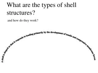
What are the types of shell structures?. and how do they work?. A shell is shaped so that it responds to loading primarily by the development of tensile and compressive membrane forces. We will review the behavior of four commonly occurring Shell Types:. Barrel Vault. Dome.

What are the types of shell structures?
E N D
Presentation Transcript
What are the types of shell structures? and how do they work? A shell is shaped so that it responds to loading primarily by the development of tensile and compressive membrane forces
We will review the behavior of four commonly occurring Shell Types: Barrel Vault Dome Hyperbolic Paraboloid (Hypar) Folded Plate An additional discussion of shell types is available at http://www.ketchum.org/ShellTandF/index.html You can browse this discussion by clicking here.
Domes The primary response of a dome to loading is development of membrane compressive stresses along the meridians, by analogy to the arch. The dome also develops compressive or tensile membrane stresses along lines of latitude. These are known as ‘hoop stresses’ and are tensile at the base and compressive higher up in the dome. Circumferential Hoop Stress (comp.) Meridional Compressive Stress Circumferential Hoop Stress (tens.) The next slides will show that additional bending stresses result in the shell as a result of restraint at the support, or unrestrained edges
Effect of Support Restraint This animation shows the additional bending near the support that results from the restraint of the support for a half-dome shell. Click to compare to the previous animation of an unrestrained shell
Bending due to edge restraint Low rise domes develop compressive membrane forces along the meridian lines, and compressive membrane forces only along the circumferential lines. This slide shows a low rise shell that does not develop tensile membrane stresses. The tensile stresses (shown in red) result from the restraint of the edge, and the resulting bending of the shell. The magnitude of these stresses would normally be sufficient to cause cracking of the shell.
In this figure, the blue color represents zones of compressive stress only. The colors beyond blue represent circumferential tensile stresses, intensifying as the colors move towards the red. A dome that is a segment of a sphere not including latitudes less than 50 does not develop significant hoop tension. The half-dome shell does develop membrane tensile stresses, below about 50 ‘north latitude.’ These are also known as ‘hoop stresses’
Effect of unrestrained edges: half-dome shell This image shows a low-rise spherical dome cut along the edges. The center part of the dome is experience primarily compression (blue). However near the disturbances along the free edge, large tensile stresses and large deformations are developing.
The shells designed and patented by Dischinger and Finsterwalder overcome the potential problem of bending due to unrestrained edges by the use of stiffening beams or diaphragms around the perimeter, and overcome the problem of circumferential tension by use of a low rise dome. The patent claim for this system says, in part, “The shells of rotation of former days had their principal stresses…in the direction of the meridians and rings only. In the dome of the present invention, the combination of dome action and bending action in the shell involves a decided change in direction and magnitude of the stresses. In a shell embodying the present invention, the principal stresses at the crown or upper portion are of the same character as in a dome, being meridinal and in circles normal to the meridians. As the eves or boundaries of the shell herein described are approached, the stresses change and are directed laterally across the corners near the columns. The maximum change is to be found at the eaves line where the shell is connected to the eaves members.”
Barrel Vault A barrel vault functions two ways compression Arch (compression) tension In the transverse direction, it is an arch developing compressive membrane forces that are transferred to the base of the arch When unsupported along its length, it is more like a beam, developing compressive membrane forces near the crown of the arch, and tensile membrane forces at the base.
Barrel Vaults A barrel vault is a simple extension of an arch shape along the width. It can be supported on continuous walls along the length, or at the corners, as in this example. If supported on the corners, it functions as an arch across the width, and as a beam, with compression on the top and tension on the bottom in the long direction. This form is susceptible to distortion.
Barrel Vault, continued As with any arch, some form of lateral restraint is required--this figure shows the influence of restraining the base of the arch--the structure is still subject to transverse bending stresses resulting from the distortion of the arch.
Barrel Vault, conclusion This structure has been provided with solid diaphragms at the ends to resist distortion. A further discussion of diaphragms for barrel-vaulted shells is available at http://www.ketchum.org/ShellTandF/index.html (click here, then click on Barrel Vaults)
The action of a barrel vault can be reviewed in light of Dischinger’s (the inventor of the thin-shell concrete structure) patent claims. ‘In contrast to the constructions of former days, in which singly curved roofs had supporting capacity only in the direction of the arch, a carrying action in the direction of the generating line of an arched shell, between widely spaced stiffening supports, is attained by the features of the present invention. It is, for instance, possible to construct a barrel shell roof of 2 inch thickness and 45 foot arch width over a span length of 150 feet or more in the direction of the generating line, if the shell, suitably stiffened by widely spaced stiffening members…is reinforced by an arrangement of bars…. ’ (Notes: the reinforcing is indicated by ‘c.’ Review the previous slides for the importance of the stiffening members)
Folded Plates Folded plate structures were widely favored for their simplicity of forming, and the variety of forms that were available. Perpendicular to the main span, the shell acts as short span plates in transverse bending In the main span direction, the shell develops membrane tension at the top and compression at the bottom, in analogy to a beam in bending Click here to compare to barrel vault
What’s wrong with this Folded Plate Structure? Compare to the discussion of barrel vaults, and see if you can tell what key element is missing from the folded plate shown. Click on the picture, if you need to see the action of the shell under load, or click on the answer below. Answer (click here) It is missing transverse diaphragms, especially at the ends.
This animation shows the effect of adding a diaphragm at the two ends and at midspan. The folded plate shell distorts much less.
Hyperbolic Paraboloid A hyperbolic paraboloid results from the division of two skew lines (the generators) into equal segments, and connecting the points on the two lines with straight lines. The hyperbolic paraboloid was favored by a number of shell designers because it is relatively easy to form (the surface can be formed using straight lines, and because it lends itself to a variety of imaginative shapes.
Hyperbolic Paraboloid, continued Both of these shapes are generated by hyperbolic paraboloids. Hypars can be laid out on a square plan—in this figure, four hypars are joined to make a regular bay that can be repeated over a large plan. Sharply skewed lines can be used to create fanciful forms.
A low-rise hyperbolic paraboloid supported only at the corners develops membrane shear stresses only (stresses in the plane of the face of the shell).
End of Section Use the navigation bar to return to Table of Contents As these idealized support conditions are never fully realized, disturbances (large bending and membrane normal stresses) result along the edges. This plot shows relatively uniform shear stresses throughout the shell, with stress concentrations at the corners, and bending deformations along the edges.