Download
1 / 35
360 likes | 577 Vues
Introduction to IEEE 802.11 Wireless LAN Standard. Huafeng Lü Sep 10, 2002 . Outline. Introduction Architecture MAC Sublayer PHY Layer Typical Product. Why Wireless LAN.

E N D
Introduction toIEEE 802.11 Wireless LAN Standard Huafeng Lü Sep 10, 2002
Outline • Introduction • Architecture • MAC Sublayer • PHY Layer • Typical Product
Why Wireless LAN • Avoid the high installation and maintenance costs incurred by traditional additions, deletions, and changes in infrastructured wired LANs. • Physical and environmental necessities • Operational environment; temporary usage
Challenges and Constraints • Frequency allocation • All users operates on a common frequency band • Must be approved and licensed by the government • Inference and reliability • Collision: begin transmission at the same time; hidden terminal; multipath fading • Security • Power consumption • Human safety • Mobility
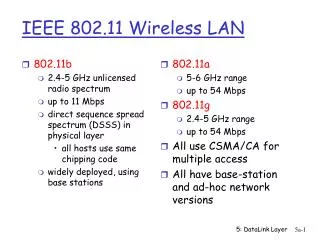
Introduction • First Standard of WLANs • IEEE Std 802.11 – 1999 • MAC sublayer, MAC management protocols and services. • 3 PHY layers: infrared, {FHSS, DHSS}@2.4GHz • 802.11a, 802.11b, 802.11g: new PHY layers
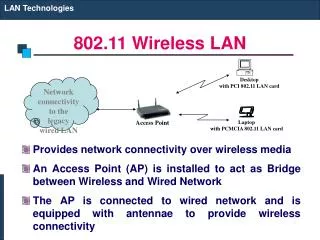
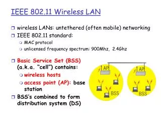
Architecture: Components • STA (Station) • Consists of a MAC and a PHY • Referred to as: network adaptor, network interface card • BSS (Basic Service Set) • Basic building block of an IEEE 802.11 LAN. • A set of STAs that communicate with one another. • A group of STAs under the direct control of a single coordination function.
Architecture: Components (cont.) • Independent BSS (IBSS) • The most basic type of a IEEE 802.11 LAN. • Each STA can communicate DIRECTLY with any others. • Often used for temporary internetworked communications, without the aid of an infrastructure. • Official name of ad-hoc network. • Infrastructure BSS (simply, BSS) • Communications are through AP: STA1 AP STA2 • AP (Access Point) • A special STA to forward communications. • Analogous to the base station in a cellular communication network.
Architecture: Figure 1 • Infrastructured • Ad Hoc
Architecture: Components (cont.) • ESS (Extended Service Set) • A set of infrastructure BSSs to extend mobility range. • APs communicate among themselves to forward traffic from one BSS to another, via DS. • DS (Distribution System) • The abstract medium for APs in different BSSs to communicate. • Can be wired, wireless network, or even not a network. • Portal • Used to integrate with other kind of IEEE 802 LANs. • A logical point, at which traffic enter from other LANs into 802.11 DS.
Architecture: Figure 2 • ESS and roaming
MAC sublayer • Provides a reliable delivery mechanism for user data over noisy, unreliable wireless medium. • Other advanced LAN services, equal to or beyond those of existing wired LANs.
MAC functions • 1. Reliable data delivery services. • By: a frame exchange protocol. • 2. Fair access control to the shared wireless medium. • By: two mechanisms, DCF & PCF. • 3. To protect data it delivers. • By: privacy service.
MAC architecture • DCF: basic, distributed, best effort. • PCF: optional, centralized, connect-oriented. • PCF are provided through the services of DCF. • DCF and PCF coexist and alternate; PCF logically sits on top of DCF.
DCF • Distributed Coordination Function • Use CSMA/CD and a random backoff time folowing a busy medium condition. • RTS/CTS, data, ACK
DCF: Carrier-sense Mechanism • To determine the state of the medium, physically and virtually. • Physically: by PHY • Virtually: by MAC, network allocation vector (NAV) mechanism. • Duration/ID fields of the RTS/CTS and the frame: the time that the medium is (to be) reserved to transmit the frame and the following ACK. • STAs adjust their NAVs according to these Duration/ID field. • The channel is marked busy if either the physical or virtual carry sensing indicates busy.
DCF: Interframe Space (IFS) • IFS: the timing intervals between frames. • 4 different IFS, increasing order: • SIFS (Short Interframe Space) • Slot_time: slightly longer than SIFS • PIFS (PCF interframe space) = SIFS + slot_time • DIFS (DCF interrame space) = SIFS + 2 * slot_time • EIFS: much longer than others • Independent of STA bit rate; fixed for a specific PHY.
DCF: Random Backoff Time • When to backoff? • If the medium is busy, the STA will defer its transmission until the medium remains idle for DIFS (if the last frame is received correctly) or EIFS (if the last frame is not received correctly). • After this defer, the STA generates a random backoff period for an additional deferral time before transmitting. • If the Backoff Timer already contains a nonzero value, the selection of a random number is not needed.
DCF: Random Backoff Time (cont.)Backoff time = rand() * slot_time • Rand(): uniform distributed random integer in [0, CW]. • CW (contention window) • In [aCWMin, aCWMax]; both bounds are PHY-specific. • Initially set to aCWMin • “Almost double” (next 2i-1) for every unsuccessful attempt to transmit • Once reaching aCWMax, remains at this value until being reset • Reset to aCWMin after every successful attempt to transmit.
DCF: Backoff Procedure • STA sets its Backoff Timer to a random backoff time. Backoff slots follows DIFS/EIFS idle period. • During each backoff slot, STA uses carrier-sense to check whether there is an activity. • NO: decrement the Backoff Timer by slot_time. • YES: Backoff Timer doesn’t decrement. Backoff procedure is suspended, until another DIFS/EIFS idle period. • Transmit whenever Backoff Timer reach zero.
DCF: MAC frame exchange RTS, CTS, data, ACK • RTS/ CTS: notify other nodes about the upcoming frame transmission. • ACK (positive acknowledegment): allow the source of the frame to determine when the frame has been successfully received by the destination. • Retransmission: scheduled by the sender if no ACK is received. • dot11RTSThreshold • If frame length > dot11RTSThreshold, RTS/CTS is used. • Otherwise, RTS/CTS is not used • Counters and timers: associated with every frame MAC attempts to transmit. Determines when to stop the retransmission of this frame. • Short/long retry counters • Lifetime timer • The time interval of SIFS is used.
PCF • Point Coordination Function • Provides contention-free frame transfer • PC (Point coordinator) • performs polling • Performed by AP within each BSS • CF-aware station • capable of operating in CFP • CFP (Contention-free period) CP (Contention period)
PCF in general • Idea: • STAs request that the PC register them on a polling list • The PC regularly polls the STAs for traffic while also delivering traffic to them. • CFP and CP alteration. • CFP: access to the medium is controlled by the PC • CP: DCF rules operate; STAs (including PC) compete for access to the medium.
PCF: CFP/CP Alternation • CFP repetition interval (CFP_Rate) • CFP_Max_Duration • Min: time of 2 max MPDUs • Max: CFP_Rate – time of max MPDU
How CFP begins • CFP begins when PC gains access to the medium in the normal procedure and transmits a Beacon frame. • The beginning of CFP may be delayed from its nominal start time, since PC must compete for the medium. • Beacon frame: include the NAV time; also sent periodically during the CFP.
During the CFP • PC transmits the Beacon frame periodically • PC delivers traffic to STAs in its BSS • PC polls STAs that have requested CF services with CF-poll. • If the STA polled has traffic to send, it transmits one frame for each CF-poll it receives; • Otherwise, the STA doesn’t response to the poll. (Or transmits a Null Function (no data) frame back to PC.)?
During the CFP (cont.) • Traffic in CFP • Frames sent from PC to STAs • followed by returning ACKs • CF-polls • ACKs and CF-polls can be piggybacked onto data frames. • PC→STA: frame + CF-poll • STA→PC: frame + ACK to previous frame • PC→STA1: frame + CF-poll to STA1 + ACK to a frame received from STA2
Preventing STAs accessing medium independently • Primary mechanism: NAV • The first Beacon contains information about the maximum expected length of the CFP • Every STA receiving this Beacon enter this length into its NAV • Backup mechanism: PIFS, for STAs that haven’t received the Beacon • PC ensures the interval between frames on the medium <= PIFS. • in DCF, idle period is DIFS = PIFS + slot_time • PC sends a frame and expects the response for at most SIFS. • If no response in SIFS, PC sends next frame before a PIFS expires after the previous transmission.
How to end a CFP • PC transmits a CF-end frame to announce the end of CFP. (Also can be piggybacked.) • STAs receiving CF-end reset theirs NAVs and then are able to begin the DCF operations.
Physical Layer • Interface between MAC and physical media • Evoluation
References • [1] ANSI/IEEE Std 802.11, 1999 Edition • [2] B. Crow, etc: IEEE 802.11 Wireless Local Area Networks. IEEE Communications Magazine, Sep 1997 • [3] Bob O’Hara; AI Petrick: IEEE 802.11 Handbook, A Designer’s Companion. Standards Information Network IEEE Press. 1999