IEEE 802.11 Wireless LAN
IEEE 802.11 Wireless LAN.

IEEE 802.11 Wireless LAN
E N D
Presentation Transcript
IEEE 802.11 Wireless LAN • All rights reserved. No part of this publication and file may be reproduced, stored in a retrieval system, or transmitted in any form or by any means, electronic, mechanical, photocopying, recording or otherwise, without prior written permission of Professor Nen-Fu Huang (E-mail: nfhuang@cs.nthu.edu.tw).
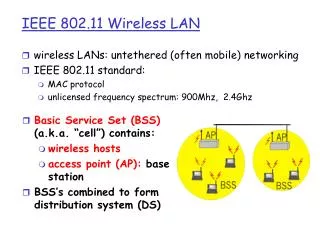
Wireless LAN Architecture • Four major differences between Wireless LAN and Wired LANs: • Destination Address Does not Equal Destination Location. • In wired LANs an address is equivalent to a physical address. In 802.11 the addressable unit is a station (STA). The STA is a message destination, but not a fixed location.
Wireless LAN Architecture • The Media Impacts the Design • The PHY layers used in 802.11are fundamentally different from wired media. 802.11 PHYs: • Have limited physical point to point connection ranges. • Use a shared medium. • Are unprotected from outside signals. • Are significantly less reliable than wired PHYs. • Have dynamic topologies.
Wireless LAN Architecture • Impact of Handling Mobile Stations • A portable station is one that is moved from location to location, but is only used while at a fixed location. • Mobile stations actually access the LAN while in motion. • Propagation effects blur the distinction between portable and mobile stations.
Wireless LAN Architecture • Interaction With Other 802 Layers • 802.11 is required to appear to higher layers (LLC) as a current 802 style LAN. Station mobility has to be handled within the MAC layer. • To meet reliability assumptions (that LLC makes about lower layers), it is necessary for 802.11 to incorporate functionality which is untraditional for MAC layers.
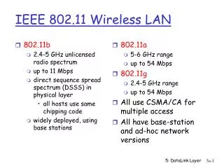
802.11Wireless LAN Characteristics • 1-108 Mbps • IEEE 802.11b is for 11 Mbps • IEEE 802.11g is for 54 Mbps • IEEE 802.11n is for 108 Mbps • IEEE 802.11 CSMA/CA Frame • Transmission Medium: Radio • CSMA/CA (Carrier Sense Multiple Access with Collision Avoidance) Protocol • Provides priority scheme • Provides delay guaranteed transmission service. (PCF reservation-based) • Bandwidth Fairness is not guaranteed. By employing the CSMA/CA protocol, the bandwidth employed by each station may be different.
802.11 Architecture Components • Wireless Medium (WM): • The medium used to implement a wireless LAN. • Station (STA): • Any device that contains an 802.11 conformant MAC and PHY interface to the wireless medium. • Station Services (SS): • The set of services that support transport of MSDUs (MAC Service Data Units) between Stations within a BSS.
802.11 Architecture Components • Basic Service Set (BSS): • A set of STAs controlled by a single CF (Co-ordination Function). • The BSS is the basic building block of an 802.11 LAN. The member stations of a BSS can communicate to each other directly. • If a station moves out of it's BSS coverage area, it can no longer directly communicate with other members of the BSS.
802.11 Architecture Components • The Independent BSS as an Ad-Hoc Network • This mode of operation is possible when 802.11 LAN stations are close enough to form a direct connection (without pre-planning).
802.11 Architecture Components • STA to AP Association is Dynamic • The association between a station and a BSS is dynamic (STAs turn on, turn off, come within range and go out of range). • To become a member of an infrastructure BSS a station must become Associated. • Distributed System Concepts: • A BSS may also form a component of an extended 802.11 network with multiple BSSs. • The architecture component used to interconnect BSSs is the Distributed System.
802.11 Architecture Components • Distribution System (DS): • A system used to interconnect a set of BSSs to create an ESS. • Distribution System Medium (DSM): • The medium used by a DS (for BSS interconnections) • 802.11 logically separates the WM from the DSM. Each logical medium is used for different purposes, by a different component of the architecture. • The DS enables mobile device support by providing the logical services necessary to handle address to destination mapping and seamless integration of multiple BSSs.
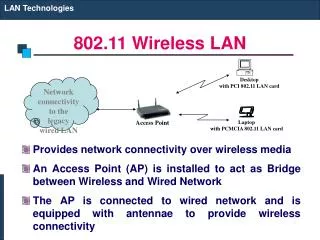
802.11 Architecture Components • Distribution System Services (DSS): • The set of services provided by the DS which enable the MAC to transport MSDUs between BSSswithin an ESS. • Access Point (AP): • Any entity that has STA functionality and provides access to the DS. • An AP is a STA which provides access to the DS by providing DS services in addition to Station Services.
802.11 Architecture Components ESS STA 1 BSS 2 STA4 BSS 1 AP STA 2 AP STA 3 擷取點 擷 取 點 Distributed System 分 散 式 系 統 AP: Access Point
802.11 Architecture Components • ESS: The large coverage network • The DS and BSSs allow 802.11 to create a wireless network of arbitrary size and complexity. • Extended Service Set (ESS): • A set of interconnected BSSs appears as a single BSS. • The ESS network appears the same to an LLC layer as an independent BSS network. • Stations within an ESS can communicate and mobile stations may move from one BSS to another (within the same ESS) transparently to LLC.
802.11 Architecture Components • Basic Service Area (BSA): • The area within which members of a BSS can communicate. • Extended Service Area (ESA): • The area within which members of a ESS can communicate. An ESA is larger than or equal to a BSA.
802.11 Architecture Components STA 1 AP BSS 1 STA 2 分 散 式 系 統 擷 取 點 AP STA 7 AP STA 3 STA 6 STA 5 BSS 2 BSS 3 STA 4 AP: Access Point
Relationship Between Services • For a station, two state variables are required to keep track: • Authentication State : Unauthenticated and Authenticated • Association State : Unassociated and Associated • Three station states are possible: • State 1 : Initial start state, Unauthenticated, Unassociated. • State 2 : Authenticated, not Associated. • State 3 : Authenticated and Associated
Relationship Between Services • These states determine the 802.11 frame types (grouped into classes) which may be sent by a station. • State 1 : Only Class 1 frames are allowed. • State 2 : Either Class1 or Class 2 are allowed. • State 3 : All frames are allowed.
Relationship Between State Variables and Services Class 1 frames State 1: Unauthenticated, Unassociated Successful Authentication DeAuthentication Time out Successful Association State 2: Authenticated, Unassociated State 3: Authenticated, Associated Disassociation Notification Classes 1,2 frames Classes 1,2,3 frames
Frame Types 起始工作站目的地工作站 • Class 1 frames • Control Frames (1) RTS (2) CTS (3) ACK (4) Poll • Management Frames (1) Probe Request/Response (2) Beacon (3) Authentication Optional RTS CTS Data ACK
Frame Types • Class 2 Frames • Data Frames • Asynchronous data. Direct data frames only (FC control bits “To DS and from DS” both false) • Management Frames (1) Privacy Request/Response (2) ATIM (Ad-Hoc Traffic Indication Map, ATIM) (3) Association Request/Response
Frame Types • Class 3 Frames • Data Frames • Asynchronous data. Indirect data frames allowed (FC control bits "To DS and from DS" may be set to utilize DS Services) • Management Frames (1) Reassociation Request/Response (2) Disassociation • CF Data Frames (Coordination Function) (1) CF DATA (2) CF DATA + ACK • CF Control Frames (1) CF END
Differences Between ESS and Independent BSS LANs • An independent BSS (IBSS) is often used to support an "Ad-Hoc" network, in which a STA communicates directly with one or more other STAs. • IBSS is a logical subset of an EBSS and consists of STAs which are directly connected. • Since there is no physical DS, there cannot be a Portal, an integrated wired LAN, or the DS Services.
Differences Between ESS and Independent BSS LANs • In an IBSS, only class 1 and class 2 frames are allowed since there is no DS in an IBSS. • The services which apply to an IBSS are the Station Services. STA 2 STA 1 STA 3 802.11 MAC/PHY IBSS
Frame and MPDU Formats • Each frame should consist of three basic components: • A MAC Header, which includes control information, addressing, sequencing fragmentation identification and duration. • A variable length Frame Body • An IEEE 32-bit CRC frame check sequence
Frame and MPDU Formats MAC Header 2 6 6 6 2 2 6 0-2304 4 位元組 Frame Control Sequence Control Sequence Control Duration/ Conn ID Addr 2 Addr 4 FCS 資料 Addr 1 Last Flag To DS From DS Power Mang. Protocol Version Retry EP Rsvd Type Subtype 2 2 4 1 1 1 1 2 1 1 位元
Frame Fields • Frame Control Field : • Protocol Version, Type, Subtype, ToDS, From DS, Last Fragment, Retry, Power Management and Element Present. • Retry : Indicates that the frame is a retransmission of an earlier frame. A station may use this indication to eliminate duplicate frames. • Power Management : Indicates power management state and buffered traffic state of the station • 00 = Active Mode (CAM or TAM), with more buffered frames • 01 = PSP - Power Save, Polling • 10 = PSNP - Power Save, No Polling • 11 = Active Mode (CAM or TAM), without more buffered frames
Frame Fields • Frame Control Field : • Duration or Connection ID : Used to distribute a value (us) that shall update the Network Allocation Vector in stations receiving the frame. • During the contention free period, this field may be replaced with a connection ID field. • Only contention free time-bounded data used a connection ID; contention based data and contention free asynchronous data do not use connection IDs.
Frame Fields • Address Fields : Indicate the BSSID, SA, DA, TA (Transmitter address), RA (Receiver address), each of 48-bit address. • Sequence Control • Dialog Token (12-bit) : An incrementing value. The same value shall be used for all fragments of the same MSDU. • Fragment Number (4-bit) : Indicates the number of each individual fragment. • Frame Body: 0 - 2304 bytes. • CRC (4 octets)
Frame Fields MSDU Frame Body MAC HDR MAC HDR Frame Body Frame Body MAC HDR MAC HDR Frame Body CRC CRC CRC CRC Fragment 1 Fragment 2 Fragment 3 Fragment 4
Format of Individual Frame Types • Control Frames • Immediately previous frame means a frame, the reception of which concluded within the prior SIFS interval. • RTS Frame Format • In an infrastructure LAN, the DA shall be the address of the AP with which the station is associated. • In an ad hoc LAN, the DA shall be the destination of the subsequent data or management frame.
Format of Individual Frame Types • CTS Frame Format • The DA shall be taken from the source address field of the RTS frame to which the CTS is a response. • ACK Frame Format • The DA shall be the address contained in the Address 2 field of the immediately previous Data or Management frame. • Poll Frame Format • The BSS ID shall be the address of the AP. The SID shall be the value assigned by the AP in the Associate Response frame.
Format of Individual Frame Types MAC Header Frame Control Duration FCS RTS Frame DA SA MAC Header Frame Control Duration DA FCS CTS Frame MAC Header Frame Control Duration DA FCS ACK Frame MAC Header Frame Control Duration BSS ID SA FCS Poll Frame
Format of Individual Frame Types • Data Frames • The contents of the Address fields shall be dependent upon the values of the To DS and From DS bits. • A station shall use the contents of Address 1 to perform address matching for receive decisions. • The DA shall be the destination of the frame (MSDU). • The RA shall be the address of the AP in the wireless DS that is the next immediate intended recipient of the frame. • The TA shall be the address of the AP in the wireless DS that is transmitting the frame.
Format of Individual Frame Types • The BSSID • The AP address, if the station is an AP or associated with an AP. • The BSS ID of the ad hoc LAN, if the station is a member of an ad hoc LAN. • Data Subtype • During the contention period: 0000 • During the contention free period • 0000, 0011, 0110, and 0111 shall only be sent by a PCF. • 0000, 0001, 0100, and 0101 may be sent by any CF-aware station.
Data Frames MAC Header Frame Control Duration/ Conn ID Fragment Number Sequence Number Addr 4 資料 FCS Addr 1 Addr 2 Addr 3 To DS From DS Addr 1 Addr 2 Addr 3 Addr 4 0 0 DA SA BSSID N/A 0 1 DA BSSID SA N/A 1 0 BSSID SA DA N/A 1 1 RA TA DA SA
MAC Architecture 免競爭式服務 (具時限傳輸) 競爭式服務 (非同步傳輸) Point Coordination Function (PCF) MAC Extent Distributed Coordination Function (DCF)
MAC Architecture • Distributed Coordination Function (DCF) • The fundamental access method for the 802.11 MAC, known as Carrier Sense Multiple Access with Collision Avoidance (CSMA/CA). • Shall be implemented in all stations and APs. • Used within both ad hoc and infrastructure configurations.
MAC Architecture • Point Coordination Function (PCF) • An alternative access method • Shall be implemented on top of the DCF • A point coordinator (polling master) is used to determine which station currently has the right to transmit. • Shall be built up from the DCF through the use of an access priority mechanism. • Different accesses of traffic can be defined through the use of different values of IFS.
MAC Architecture • Shall use a Point IFS (PIFS) < Distributed IFS (DIFS) • Point coordinated traffic shall have higher priority to access the medium, which may be used to provide a contention-free access method. • The priority access of the PIFS allows the point coordinator to seize control of the medium away from the other stations.
MAC Architecture • Coexistence of DCF and PCF • Both the DCF and PCF shall coexist without interference. • They are integrated in a superframe in which a contention-free burst occurs at the beginning, followed by a contention period.
MAC Architecture 超級訊框 Super Frame 免競爭訊框 需競爭訊框
Distributed Coordination Function • Allows for automatic medium sharing between PHYs through the use of CSMA/CA and a random backoff time following a busy medium condition. • All directed traffic uses immediate positive ack (ACK frame) where retransmission is scheduled by the sender if no ACK is received. • Carrier Sense shall be performed both through physical and virtual mechanisms.
Distributed Coordination Function • The virtual Carrier Sense mechanism is achieved by distributing medium busy reservation information through an exchange of special small RTS and CTS frames (contain a during field) prior to the actual data frame. Unicast only, not used in multicast/broadcast. • The use of RTS/CTS is under control of RTS_Threshold (payload length, under which without any RTS/CTS prefix). • All stations are required to be able to receive any frame transmitted on a given set of rates, and must be able to transmit at (at least) one of these rates. This assures that the Virtual Carrier Sense mechanism still works on multiple rates environments.
Distributed Coordination Function • Physical Carrier Sense Mechanism • A physical carrier sense mechanism shall be provided by the PHY. • Virtual Carrier Sense Mechanism • Provided by the MAC, named Net Allocation Vector (NAV), which maintains a prediction of future traffic based on duration information announced in RTS/CTS frames.
Distributed Coordination Function • MAC-Level Acknowledgments (Positive Acknowledgment) • To allow detection of a lost or errored frame an ACK frame shall be returned immediately following a successfully received frame. The gap between the received frame and ACK frame shall be SIFS. • The frame types should be acknowledged with an ACK frame: • Data • Poll • Request • Response • The lack of an ACK frame means that an error has occurred.
Distributed Coordination Function --Inter-Frame Space (IFS) • A station shall determine that the medium is free through the use of carrier sense function for the interval specified. • Three different IFS's are defined to provide priority levels. • Short-IFS (SIFS) • Shall be used for an ACK frame, a CTS frame, by a station responding to any polling, and between frames in the sequences described in Page 41. • Any STA intending to send only these frame types shall be allowed to transmit after the SIFS time has elapsed following a busy medium.
Distributed Coordination Function --Inter-Frame Space (IFS) • PCF-IFS (PIFS) • Shall be used only by the PCF to send any of the Contention Free Period frames. • The PCF shall be allowed to transmit after it detects the medium free for the period PIFS, at the start of and during a CF-Burst. • DCF-IFS (DIFS) • Shall be used by the DCF to transmit asynchronous MPDUs. • A STA using the DCF is allowed to transmit after it detects the medium free for the period DIFS, as long as it is not in a backoff period.
Distributed Coordination Function --Random Backoff Time • Before transmitting asynchronous MPDUs, a STA shall use the carrier sense function to determine the medium state. • If busy, the STA shall defer until after a DIFS gap is detected, and then generate a random backoff period for an additional deferral time (resolve contention). Backoff time = INT(CW * Random()) * Slot time
Distributed Coordination Function --Random Backoff Time Where CW = An integer between CWmin and CWmax Random() = Slot Time = Transmitter turn-on delay + medium propagation delay + medium busy detect response time CWmax 127 255 255 63 31 CWmin 15 7 第三次重送 初始值 第二次重送 第一次重送