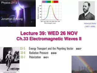
Lecture 13 Electromagnetic Waves Ch. 33
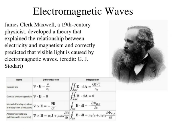
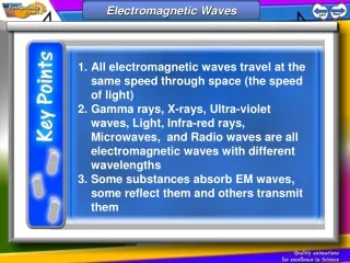
Lecture 13 Electromagnetic Waves Ch. 33. Cartoon Opening Demo Topics Electromagnetic waves Traveling E/M wave - Induced electric and induced magnetic amplitudes Plane waves and spherical waves Energy transport snd Intensity of a wave Poynting vector Radiation Pressure produced by E/M wave

Lecture 13 Electromagnetic Waves Ch. 33
E N D
Presentation Transcript
Lecture 13 Electromagnetic Waves Ch. 33 • Cartoon • Opening Demo • Topics • Electromagnetic waves • Traveling E/M wave - Induced electric and induced magnetic amplitudes • Plane waves and spherical waves • Energy transport snd Intensity of a wave Poynting vector • Radiation Pressure produced by E/M wave • Polarization • Reflection, refraction,Snell’s Law, Internal reflection • Prisms and chromatic dispersion • Polarization by reflection-Brewsters angle • Elmo • Polling
To investigate further the properties of electromagnetic waves we consider the simplest situation of a plane wave. A single wire with variable current generates propagating electric and magnetic fields with cylindrical symmetry around the wire. If we now stack several wires parallel to each other, and make this stack wide enough (and the wires very close together), we will have a (plane) wave propagating in the z direction, with E-field oriented along x, E = Ex (the current direction) and B-field along y B=By(Transverse waves)
How the fields vary at a Point P in space as the wave goes by
Faraday’s Law of Induction Maxwell’s Law of Induction Changing electric field induces a magnetic field Changing magnetic field induces a electric field Electromagnetic Wave Self Generation
Magnitude of S is like the intensity U is the energy carried by a wave
Relation of intensity and power for a Spherical Wave - Variation of Intensity with distance A point source of light generates a spherical wave. Light is emitted isotropically and the intensity of it falls off as 1/r2 Let P be the power of the source in joules per sec. Then the intensity of light at a distance r is Lets look at an example
(c) The power of the source is 15. The maximum electric field at a distance of 10 m from an isotropic point light source is 2.0 V/m. Calculate (a) the maximum value of the magnetic field and (b) the average intensity of the light there? (c) What is the power of the source? (a) The magnetic field amplitude of the wave is (b) The average intensity is
Nothing is known to travel faster than light in a vacuum However, electrons can travel faster than light in water. And when the do the electrons emit light called Cerenkov radiation
Momentum and Radiation Pressure Momentum = p What is the change in momentum of the paper over some time interval? Light beam c paper p=U/c p=0 1) Black paper absorbs all the light 2) Suppose light is 100% reflected From this we define the pressure
Radiation Pressure Pr Want to relate the pressure Pr felt by the paper to the intensity of light For 100% absorption of light on the paper For 100% reflection of light
Problem 21 What is the radiation pressure 1.5 m away from a 500 Watt lightbulb?
Polarization of Light • All we mean by polarization is which direction is the electric vector vibrating. • If there is no preferred direction the wave is unpolarized • If the preferred direction is vertical, then we say the wave is vertically polarized
A polarizing sheet or polaroid filter is special material made up of rows of molecules that only allow light to pass when the electric vector is in one direction. Pass though a polarizing sheet aligned to pass only the y-component
Unpolarized light Resolved into its y and z-components The sum of the y-components and z components are equal
Intensity I0 Pass though a polarizing sheet aligned to pass only the y-component Malus’s Law One Half Rule Half the intensity out
Malus’s Law Light comes from here Intensity is proportional to square of amplitude y
Sunglasses are polarized vertically. Light reflected from sky is partially polarized and light reflected from car hoods is polarized in the plane of the hood Sunglass 1 Sunglass 2 Rotate sun glass 2 90 deg and no light gets through because cos 90 = 0
Polaroid Material Transmits Light Yes Light No
Chapter 33 Problem 33 In the figure, initially unpolarized light is sent through three polarizing sheets whose polarizing directions make angles of 1 = 40o, 2 = 20o, and 3 = 40o with the direction of the y axis. What percentage of the light’s initial intensity is transmitted by the system? (Hint: Be careful with the angles.) The polarizing direction of the third sheet is 3= 40o counterclockwise from the y axis. Consequently, the angle between the direction of polarization of the light incident on that sheet and the polarizing direction of the sheet is 20o + 40o = 60o. The transmitted intensity is
Chapter 33 Properties of Light Continued • Law of Reflection • Law of Refraction or Snell’s Law • Chromatic Dispersion • Brewsters Angle
Lab06 Lab07 Lab06 Lab08
Dispersion: Different wavelengths have different velocities and therefore different indices of refraction. This leads to differentrefractive angles for different wavelengths. Thus the light is dispersed.The frequency does not change when n changes.
n2=1.33 Snells Law Red θ1 n1=1.00 θ2
Chapter 33 Problem 49 In Figure 33-51, a 2.00 m long vertical pole extends from the bottom of a swimming pool to a point 90.0 cm above the water. Sunlight is incident at angle θ = 55.0°. What is the length of the shadow of the pole on the level bottom of the pool?
1 l1 air water 2 l2 shadow L x Chapter 33 47. In the figure, a 2.00-m-long vertical pole extends from the bottom of a swimming pool to a point 50.0 cm above the water. What is the length of the shadow of the pole on the level bottom of the pool?
1 l1 air water 2 l2 shadow L x Consider a ray that grazes the top of the pole, as shown in the diagram below. Here 1 = 35o, l1 = 0.50 m, and l2 = 1.50 m. The length of the shadow is x + L. x is given by x = l1tan1 = (0.50m)tan35o = 0.35 m. L is given by L=l2tan Use Snells Law to find
1 l1 air water L is given by 2 l2 shadow L x Calculation of L According to the law of refraction, n2sin2 = n1sin1. We take n1 = 1 and n2 = 1.33 The length of the shadow is L+x. L+x = 0.35m + 0.72 m = 1.07 m.
Why is light totally reflected inside a fiber optics cable? Internal reflection
Equilateral prism dispersing sunlight late afternoon. Sin θrefr= 0.7nλ
How much light is polarized when reflected from a surface? Polarization by Reflection: Brewsters Law
What causes a Mirage eye sky 1.09 1.09 1.08 1.08 1.07 1.07 Index of refraction 1.06 Hot road causes gradient in the index of refraction that increases as you increase the distance from the road