Download
1 / 36
360 likes | 393 Vues
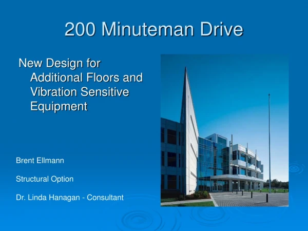
200 Minuteman Drive. New Design for Additional Floors and Vibration Sensitive Equipment. Brent Ellmann Structural Option Dr. Linda Hanagan - Consultant. Project Players. Owner- Brickstone Properties Architects-Burt Hill Kosar Rittleman Associates

E N D
200 Minuteman Drive New Design for Additional Floors and Vibration Sensitive Equipment Brent Ellmann Structural Option Dr. Linda Hanagan - Consultant
Project Players • Owner- Brickstone Properties • Architects-Burt Hill Kosar Rittleman Associates • Structural Engineers- Atlantic Engineering Services • MEP Firm- H. F. Lenz Co. • C M Firm- Gilbane Building Company • Geotechnical Firm- Miller Engineering and Testing, Inc.
Existing Building Conditions • Location: Andover, MA • 3 stories with 260,000 square feet of office space • Cost: $15 million
Existing Structure • Composite floor system • K joist roof framing • Square footings and strip footings • Braced frames PICTURES
Existing Mech./Elec./Arch. • Mechanical • 6 air handling units with DX cooling coils (25,000 CFM) and ducted supply with a plenum return VAV system • 2 cast iron- sectioned boilers (Gross Output – 2103 MBH) • Electrical • Main switchboard is a 480 Volt/2500 Amp switchboard • Typical light is a three tube FO32/T-8 fluorescent fixture • Architectural • Insulated metal panels, with low-E reflective glazing, along the curved northern façade • Southern facing wall is a limestone veneer
Goals of New Design • Maintain owner’s original wishes while adding additional floors • All steel building • Open office plan to allow for future tenant changes • Improve performance of floor under vibration excitement due to walking for sensitive equipment • Allow for varying use of building by multiple tenants at once
General Work Completed • Structural (Emphasis) • Floor Vibration Study • Column Design • Foundation Design • Braced Frame Design • Foundation Design • Mechanical (Breadth) • Increased Air Handling Capacity • Duct Sizing • Electrical (Breadth) • Increased switchboard capabilities • Increased direct feed to mechanical equipment
Presented Information • New Building Height and Floor Determination By Code • Brief Overview of Mechanical and Electrical Design • Floor Design for Sensitive Equipment • Column Design • Braced Frame Design • Foundation Design
Original Building • 14’-7” floor to floor height • Roof Height??? • 10’-0” tall clerestory • 2 Mechanical Penthouses
New Design • Floor to floor heights???? • 10’-0” clerestory maintained • New Building height • Under code height
New Design Elevation New Building Size: ####### Square Feet
Mechanical Design • New Requirements • New Equipment Sizes and Numbers • New Duct Sizes
Electrical Design • New Requirements • New Switch Board Sizes and layouts
Structural Design • Floor Vibration Study • Column Design • Braced Frame Design • Foundation Design
Floor Vibration Criteria • Goal: Allow for a variety of technology and research based companies to use this facility. • Design carried out using Design Guide 11 and the development of a spreadsheet
Compared Systems Original System Original System
Column Design • 2 Types of Columns • Columns with mechanical equipment on top • Columns without mechanical equipment on top
Typical Columns Mechanical Column Non-Mechanical Column
Column Splices • Splices located three feet above floor level of 3rd floor
Braced Frame Design • Structure is located in a zone of high seismic activity • Earthquake forces govern lateral resisting system design Wind Loads Earthquake Loads
Critical N-S Frame • Columns: • Braces: • Beams:
Critical E-W Frame • Columns: • Braces: • Beams:
Foundation Design • Square footings used under columns and strip footings used around perimeter of building • Engineered soil placed under footings • Compressive Strength = 6,000 psf • 3,000 psi concrete used for all footings
Uplift Force • Problem: • Earthquake forces develop large uplift on footings • Solution: • Grade Beam attaching to other footings
Grade Beam • 3’-0” x 5’-0” beam spanning over four square footings • Reinforcement!?!?!?!?!?!