Download
1 / 15
160 likes | 194 Vues
Understand SSR concerns, causes, and mitigation strategies for electromechanical resonance. Learn about SSR relay options, countermeasures, and protection methods. Explore case studies and applications. Elevate your power systems expertise.

E N D
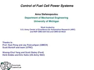
SSR Control of Power Systems By Colin EJ Bowler Instrumentation Technology Inc. September 9, 2013 ERCOT
Electromagnetic Resonance Concerns • Causes • SSR from series capacitor application • Electrical self excitation • Torsional interaction • Transient resonance • Device dependent torsional interaction • Control design ramification for: • HVDC, SVC, UPFC • Excitation systems • Super synchronous resonance • Torsional modes too close to f0 and 2*f0 frequency • Strong coupling to generator torque • Negative sequence torque transients • Unbalanced transmission faults • Breaker high-speed reclosing
SSR Torsional InteractionDamping v.s. Series Compensation Level • An unstable electric & mechanical response • Limited by magnetic saturation or plasticity • A broad band phenomena 0->60 Hz • Occurs over a wide range of series compensation • Mitigated by damping or filtering
SSR Transient Response • Mostly a post fault phenomena – torsional interaction driven by post fault resynchronization • Mechanical response integrates the electrical response at resonance • Even when stable, event will produce severe shaft fatigue
Application RULES for SSR • Must be Base Case Stable • Probability of SSR should be low • N-2 or better at onset • Must NOT Operate near Resonance • Control Shaft Torque • Keep same as equivalent uncompensated system • SSR Relay Only Protection • Only when probability of SSR is very low • Backing up calculated expectation of stability • Backing up switching countermeasures • Load Dependent Capacitor switching • SSR Relay only for backing up primary SSR control
Quantification of SSR • Level of Torsional Destabilization • Excess over positive damping • Turbine Positive Damping 0.05 to 0.1 rad/sec • Negative Damping due to SSR • 500 kV – 3 Rad/sec • 345 kV - 1 Rad/sec • Level of Shaft Torque • Excess over High Cycle Fatigue Torque • 1 to 3 Times on uncompensated system • Do not exceed levels for uncompensated system
SSR Protection Options • Instantaneous electro-magnetic torque • Instantaneous three phase voltages • Instantaneous three phase line current • Subtract stator iR drops from voltage • Integrate to measure magnetic flux • Multiply flux by current • Instantaneous velocity response • Each end of TG set • Basic Elements of Torsional Protection & Monitoring • SSO – Subsynchronous Time over-current • SMF – Subsynchronous Time over-velocity • DMF – Subsynchronous Time over-acceleration • Monitoring internal stress and fatigue
SSR Relay Qualities • Dependability • Always Trips when required • Security • Never False Trips • Undependable • Does NOT trip when required • Insecure • Trips when NOT required (FALSE)
Instrumentation Technology Experience • Original Developer of SMF Protection in US • Developed DMF Observer Protection • Commissioned by SCE • First use on Mohave Plant • Installed, Operating, Ordered - 24 systems • 16 gas turbines • 4 Nuclear • 4 Fossil
The End • THANK YOU Colin EJ Bowler President IT Inc. cbowler@inst-tech.com (919)-656-5853 m (919)-380-1039 p
DMF Protection for Combined Cycle Group • SMF & DMF Protection • Operator Interface • Velocity Target vs Mode • Acceleration Targets vs Mode • Trip Target • Shaft Torque Display
Post Event Data Evaluation • Enhanced replacement for generator oscillograph • 120 Samples per cycle • 32 Channels Analog • 24 channels digital input • 24 channels digital output • GPS Time synchronized • Available with phasor measurement sub-system • COMTRADE file generation • Arbitrary long events • Nonvolatile storage • Windows human interface • Independent from protection system • Easy to understand & use
SSR Protection • Traditional methods - SMF • Filter modal response from velocity • Inverse time over-velocity • Cannot mitigate resonance due to filter delay • Observer based methods – DMF • Calculate response where inaccessible to direct measurement • Measure modal torque without filter delay • Inverse time over-velocity and acceleration • Can trip before max response is reached • Extremely Dependable & Secure • A class of both protection and mitigation for SSR • Valuable for super synchronous response observation • Eliminates false trip and high associated cost