Evaluating Quality Properties of Component-based Software Architectures
300 likes | 458 Vues
Evaluating Quality Properties of Component-based Software Architectures. Egor Bondarev Michel Chaudron System Architecture & Networking Group Peter de With (TUE & LogicaCMG) Video Coding & Architectures Group Technische Universiteit Eindhoven, The Netherlands. Outline.

Evaluating Quality Properties of Component-based Software Architectures
E N D
Presentation Transcript
Evaluating Quality Properties of Component-based Software Architectures Egor Bondarev Michel Chaudron System Architecture & Networking Group Peter de With (TUE & LogicaCMG) Video Coding & Architectures Group Technische Universiteit Eindhoven, The Netherlands
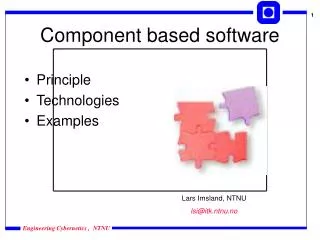
Outline • Introduction & Context • Problem statement • Approach • scenario-based predictable assembly • Conclusion
Context • Robocop/Space4U projects • high volume embedded systems • mobile phones (Nokia), DVD players (Philips) • multimedia processing and control systems • Open component-based framework for resource constrained systems • Open at run-time: software components may come and go • Requirements: Robustness, Upgrading/extension, and Trading
Problem Statements (1) Can we design a system using third-party software components that provides the required extra-functional quality (XFQ) properties? (2) How can we ensure that a system will continue to provide the XFQs while third-party software components are added and removed? designtime runtime Third party software components are black-box i.e. no access to internals/code. For reasons of efficiency of reuse or protection of IP
Required eXtra-Functional Qualities • Does the system (continue to) behave properly? • Can the system execute tasks in a timely manner? • Is there sufficient CPU power? • Does the system have sufficient memory for the tasks? • Is there no malicious use of resources? • Typical system quality attributes: • Performance (timeliness, throughput) • Resource use (processor, memory, bus) • Reliability • Cost
Predictable Assembly Can we predict the quality attributes of a system based on the properties of its components? Candidate Quality Properties: Efficiency, Footprint, Responsiveness, Scalability, Schedulability, Timeliness, CPU utilization, Latency, Throughput, Concurrency, Accuracy, Accountability, Testability, Traceability, Analyzability, Distributeability, Availability, Confidentiality, Integrity, Reliability, Safety, Security, Affordability, Extensibility, Tailorability What do we need to specify per component in order to be able to predict system properties?
Problem Instance: Cost Derive cost of a system from cost of its parts. C1 25 S 42 C1 C2 C2 17 Other example: static memory use More complicated: real-time / timeliness properties
Problem Instance: Timeliness Derive timing of a system from timing of its parts. C1 25 sec S ? C1 C2 C2 17 sec It depends … • way of connecting components (seq, parallel) • shared resources (and their scheduling) • synchronization
Characteristics of Target Systems • Systems may be event-triggered and time-triggered • SW components may be active or passive • System support multi-threaded applications • System supports dynamic resource (CPU, memory) allocation • There may be dependencies between tasks • control- and data-dependencies • synchronization constraints: • task precedence, rendezvous, mutexed operations • System are designed by composing ‘black box’ software- and hardware-components
Requirements on the analysis method • Method should allow • low modelling effort • a trade-off between modeling effort and accuracy • resource-efficient analysis (for run-time analysis) • Nice to have: compatibility with • Unified Modelling Language (UML (2.0)) • IEEE Stnd. 1471 Recommended Practice for Architectural Description of Software-Intensive Systems
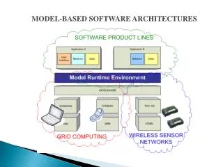
Solution Approach Based on the following concepts • Models for both software- and hardware components. • Scenarios-based evaluation • The designer can focus on critical aspects of system behaviour. • Simulation of scenarios
Proposed Solution Major assumptions: • Software component models and hardware component models are available at system design time. • Resource usage (execution time, bus load) of each component operation is defined by a model. • The architect is able to identify a set of critical execution scenarios for an architecture.
Example Problem: Car Navigation System (CNS) Environment Logical View MMI = Man-Machine Interface RAD = Radio controller NAV = Navigation Software
(A) (B) 22 MIPS 22 MIPS 72 kbps 57 kbps MMI_Inst MMI_Inst 113 MIPS 113 MIPS 11 MIPS 11 MIPS NAV_Inst RAD_Inst NAV_Inst RAD_Inst 72 kbps 260 MIPS MMI_Inst 260 MIPS 130 MIPS 113 MIPS 22 MIPS NAV_Inst MMI_Inst RAD_Inst NAV_Inst MMI_Inst 72 kbps 72 kbps RAD_Inst RAD_Inst NAV_Inst (E) (D) (C) CNS: Architectural Alternatives Optimal alternatives in terms of: Resource usage + Performance + Reliability + Cost + …
Robocop Component Model • A Component is a set of models • Provided by the supplier • Executable Components have Services • Services have provides and requires interfaces • Interfaces have operations
Behaviour forms a partial call graph ? I2 c2 Component behaviour model service c2 requires I2 requires I3 provides I1{ operation f uses I2.g uses I3.h behaviour operation f calls: I2.g* I3.h } Service is run-time unit of structuring Behaviour is modeled per operation Variable & data-dependentcall sequences can be modelled
Resource Model ResourceModel_MPEG4Decoder_Component resource use operationdecodeFrame() cpu claim max = 1E7 cycles aver = 1E5 cycles min = 1E4 cycles mem claim = 10 KB mem release = 3 KB Different resource models may be supplied fordifferent (classes) of processors (RISC, VLIW, …)
Model Assembly Phase 0: Define Scenarios • A scenario is a setting of • A set of one or more triggers • A specific configuration of a system • Trigger t fires every s msec • this trigger starts operation ‘f’ of interface I
Model Assembly Phase 1: Structure • At bind-time, the decision is made which services are composed to provide the implementation of an interface • A call to operation ‘f’ is started f • f is provided by s1 • s1 needs g from I2 and h from I3 • I2 (hence g) is provided by s2 • s2isdone • I3 (hence h) is provided by s3 • s3 needs j from I4 • I4 (hence j) is provided by s4 • s4 is done s1 g h s2 s3 j s4
g g h h j j Model Assembly Phase 2: Logical Behaviour Combine the behaviour models of the operations used Press button ‘f’ operation f calls: S2.g; S2.g; S3.h; S3.h f s1 s1 g h s2 s2 s3 s3 j s4 s4
g g h h j j Model Assembly Phase 3: Integrate Resource Claims f s1 s1 g h s2 (cl,rl) (cl,rl) s2 s3 s3 (cl,rl) (cl,rl) j s4 s4 (cl,rl) (cl,rl)
s1 T1 g g h h p q s2 x y z T2 (cl,rl) (cl,rl) (cl,rl) s3 T3 (cl,rl) (cl,rl) (cl,rl) j j r s4 T4 (cl,rl) (cl,rl) (cl,rl) Model Assembly Phase 4: Define concurrency behaviour Mapping of Logical behaviour onto Tasks U1 v v U2 (cl,rl) (cl,rl) w w U3 (cl,rl) (cl,rl)
s1 T1 U1 g g h h p q v v s2 T2 U2 (cl,rl) (cl,rl) (cl,rl) (cl,rl) (cl,rl) s3 T3 (cl,rl) (cl,rl) (cl,rl) j j r w w s4 T4 U3 (cl,rl) (cl,rl) (cl,rl) (cl,rl) (cl,rl) Phase 5: Resource Scheduling Resource Management Policy e.g. scheduler e.g. EDF, CBS, … v w v v p q r g g h h (cl,rl) (cl,rl) (cl,rl) (cl,rl) (cl,rl) (cl,rl) (cl,rl) (cl,rl) (cl,rl) (cl,rl) (cl,rl) (cl,rl) Resource .. etc 17 253 42
Bus load Memory usage Simulation time Simulation time Scenario Simulation Simulation time
DB Checker Parser Analyser DB Creator DB Filler Inheritance Relator S C1 C2 RM platform Summary of Recipy for Predictable Assembly 0. Definition of Scenarios C1 C2 1. Composition of System Structure • Composition of Logical Behaviour • of whole system Analyser DB Creator DB Filler Inheritance Relator x y z resource R claim 100 release 100 • Composition of Execution Behaviour • - tasks • - resource mng policies system model • Analyse
(A) (B) 22 MIPS 22 MIPS 72 kbps 57 kbps MMI_Inst MMI_Inst 113 MIPS 113 MIPS 11 MIPS 11 MIPS NAV_Inst RAD_Inst NAV_Inst RAD_Inst 72 kbps 260 MIPS MMI_Inst 260 MIPS 22 MIPS NAV_Inst RAD_Inst MMI_Inst 72 kbps RAD_Inst NAV_Inst (E) (C) 130 MIPS 113 MIPS MMI_Inst NAV_Inst 72 kbps RAD_Inst (D) Evaluating Architectural Alternatives Sw Component Hardware node Hardware link
Evaluation of the method • Predict XF-Q properties based on black-box components • Compositional (supports third-party binding) • Method can be used throughout development cycle (design / implementation / run-t) with incremental accuracy • The method can be applied to different types of resources • Supports dynamic resource management policies • The method can support different types of analyses • (Worst-Case, Best-Case, …) • Scenario’s • Do not give 100% guarantees as usual in formal methods • Do allow incremental accuracy: focus on what is important