Download
1 / 106
1.06k likes | 1.24k Vues
History. Start CATV Business with the name of Bando Electronic Industry 1989 Korean Type Dual Sound Two Carrier Modulator Development CATV Head-end OEM Contract with LG Information & Comm. CATV FM Modulator / Demodulator Development CATV Head-end Product Qualified by KT (Korea Telecom)

E N D
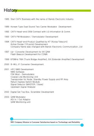
History • Start CATV Business with the name of Bando Electronic Industry • 1989 Korean Type Dual Sound Two Carrier Modulator Development • CATV Head-end OEM Contract with LG Information & Comm. • CATV FM Modulator / Demodulator Development • CATV Head-end Product Qualified by KT (Korea Telecom) • Active Divider (16 ports) Development • Company Name was changed with Bando Electronic Communication.,Ltd • 1997 Up- Converter Development for 64 QAM • Flash Beacon Development for CDMA • 1999 870MHz TBA (Trunk Bridge Amplifier), EA (Extender Amplifier) Development • B-WLL IF Converter Development • HFC NMS Development • NMS Software • FSK Mod – Demodulator • Coaxial Line Monitoring Unit • Transponder for Node, Standby Power Supply and RF Amp • Return Ingress Switch Module • Signal Selector (MASTER / Slave) • Upstream Signal Analyzer • 2002 Digital Set Top Box, Scrambler Development • QAM Modulator • ASI In / Out Adaptor • QAM Monitoring unit BEC Company Mission is Customer Satisfaction based on Technology and Reliability
Contents ▷ Part I TV AM Modulator (3) ▷ Part II TV Signal Processor (18) ▷ Part III TV Digital Signal Processor (33) ▷ Part IV Local Device (36) ▷ Part V Line Amplifier (47) ▷ Part VI Indoor Amplifier (73) ▷ Part VII Passive Device (78) ▷ Part VIII HFC NMSl (81)
TV AM Modulator Superior Grade ▶ BDH 3750 ▶ BDH 3751 (Agile) ▶ BDH 2750 ▶ BDH 2751 (Agile) ▶ BMD 2510 ▶ BMD 2510AG (Agile) ▶ BMD 3000W (Agile) High Grade TV AM Modulator Mid Grade Low Cost Type
Modulator■ BDH 3750 Dual Sound TV Modulator (Superior Grade) ■Modulator process a baseband video and audio signal to produce RF signal at a selected CATV Channel frequency. ■BDH 3750 utilizes ASIC technology that delivers superior performance signal and provides variable user friendly functions. ■Recognition ID for Mono, Dual and Stereo is inserted in Line 11~21 of Field 2 video signal (Line 21 at factory setting) Description Feature ■MOIC (Korean Ministry of Information and Communication) type approval product (11B-KOR-D11-98-0347) ■Korean Type Dual Sound Two Carrier product. ■ Automatic DSC(Dual Sound Coder) function installed for recognition ID (Manual function too) ■ Using High performance Saw Filter ■ Using X-TAL ( better reliability than PLL ) ■Group Delay EQ installed to get clear color ■ ALC function by one chip Micom (Optional) A.L.C : Audio Level Control board for unstable audio input level ▶RF OUTPUT ▷Output Freq 54 ~ 550MHz (Fixed 1CH) ▷Freq Stability : ± 5KHz ▷Video Output Level : 40 ~60dBmV ▷Audio 1 Output : -16dB ± 1dB( for Video Level ) ▷Audio 2 Output : -23dB ± 1dB(for Video Level ) ▷Spurious :< -60dB ▷Return Loss : <-16dB ▷Impedance : 75Ω unbal ▶VIDEO INPUT ▷Input Level : 1 Vp-p ± 5dB ▷Impedance : 75Ω , unbalance ▷Return Loss : < -35dB ▷Connector : BNC-TYPE ▶AUDIO INPUT ▷Input Level : 0dBm ± 10dB ▷Impedance : 600Ω , Balance ▷Connector : CANNON-TYPE Data Sheets ▶AUDIO Spec ▷Freq Response : ± 1dB ▷Harmonic Distortion : <0.5% ▷L/R Isolation : >55dB ▷Stereo Isolation : >30dB ▷Audio 1 Freq Devi : ±25KHz ▷Audio 2 Freq Devi : ±27.5KHz ▷Signal to Noise : >60dB ▶VIDEO Spec ▷Freq Response : ± 1dB ▷Modulation Depth : 87.5% ▷Gain : ±4 IRE ▷Delay : ±33ns ▷Field Time Distortion : <1% ▷Line Time Distortion : <1.7 IRE ▷Short Time Distortion : <2.7% ▷Differential Gain : <3% ▷Differential Phase : <1.3˚ ▷S/N Ratio : > 60dB ▶GENERAL ▷DIMENSION 483 X 44 X 440 (W x H x Dmm) ▷Input Power : 110 / 220V 60Hz ▷Power Consumption : <40W
Modulator■ Data Sheets ⑤ ④ ② ③ ⑥ ⑧ ⑩ ⑮ ⑬ ① ⑦ ⑨ ⑫ ⑭ ⑪ ① Power : Input Power Indicator ② Video Input Test Point : Baseband Video Input Level Test Point (by Oscilloscope, etc.) ③ Video Modulation Depth Adjustment ④ Video Input LED : LED ON when input Audio signal is higher than user setting level ⑤ Left Audio Modulation Depth Adjustment ⑥ Left Audio Input LED : LED ON when input Audio signal is higher than user setting level ⑦ Audio A.L.C LED : A.L.C On/Off Indicator ⑧ Right Audio Input LED : LED ON when input Audio signal is higher than user setting level ⑨ Right Audio Modulation Depth Adjustment ⑩ Audio Carrier level Adjustment ⑪ Auto Button : Mono, Stereo, or Dual audio are automatically recognized and let the recognized control signal be inserted to audio output signal ⑫ Mono Button : Let the audio output signal be Mono regardless of input control signal ⑬ Stereo Button : Let the audio output signal be Stereo regardless of input control signal ⑭ Dual Button : Let the audio output signal be Dual regardless of input control signal ⑮ RF Output Level Adjustment ④ ③ ⑤ ⑬ ② ⑭ ⑥ ⑧ ⑩ ① ⑦ ⑨ ⑫ ⑪ ① F-Type RF Output Port ② RF Output Port Test Point (-20dB) ③ Audio IF Input Port (F-Type) ④ Audio IF Output Port (F-Type) ⑤ Video IF Input Port (F-Type) ⑥ VIDEO IF Output Port (F-Type) ⑦ Audio A.L.C switch (Audio Level Control Switch : Optional ) ⑧ Audio Input Port (Left) : Baseband Audio Input Port (Cannon-Type) ⑨ Audio Input Port (Right) : Baseband Audio Input Port (Cannon-Type) ⑩ Video Input Port : Baseband Video Input Port (BNC-Type) ⑪ Power ON / OFF Switch ⑫ Power Input and Fuse Box : AC110/ 220V Power Input Port and Fuse Box (including Fuse) ⑬ Power Selector : 110VAC or 220VAC Power Selector ⑭ GND : GND Port
Modulator■ BDH 3751 Agile Dual Sound TV Modulator (Superior) Description ■Modulators process a baseband video and audio signal to produce RF carrier on any channel from 54 ~ 550MHz. ■BDH 3751 utilizes ASIC technology that delivers superior performance signal and provides variable user friendly functions. ■Recognition ID for Mono, Dual and Stereo is inserted in Line 11~21 of Field 2 video signal (Line 21 at factory setting) Feature ■Korean Type Dual Sound Two Carrier product. ■ Automatic DSC(Dual Sound Coder) function installed for recognition ID (Manual function too) ■ Using High performance Saw Filter ■ Using X-TAL ( better reliability than PLL ) ■Group Delay EQ installed to get clear color ■ ALC function by one chip Micom (Optional) A.L.C : Audio Level Control board for unstable audio input level Data Sheets ▶RF OUTPUT ▷Output Freq : Agile 54 ~ 550MHz ▷Freq Stability : ± 5KHz ▷Video Output Level : 40 ~60dBmV ▷Audio 1 Output : -16dB ± 1dB( for Video Level ) ▷Audio 2 Output : -23dB ± 1dB(for Video Level ) ▷Spurious :< -55dB ▷Return Loss : <-14dB ▷Impedance : 75Ω unbal ▶VIDEO INPUT ▷Input Level : 1 Vp-p ± 5dB ▷Impedance : 75Ω , unbalance ▷Return Loss : < -30dB ▷Connector : BNC-TYPE ▶AUDIO INPUT ▷Input Level : 0dBm ± 10dB ▷Impedance : 600Ω , Balance ▷Connector : CANNON-TYPE ▶AUDIO Spec ▷Freq Response : ± 1dB ▷Harmonic Distortion : <0.5% ▷L/R Isolation : >55dB ▷Stereo Isolation : >30dB ▷Audio 1 Freq Devi : ±25KHz ▷Audio 2 Freq Devi : ±27.5KHz ▷Signal to Noise : >60dB ▶VIDEO Spec ▷Modulation Depth : 87.5% ▷Gain : ±10 IRE ▷Field Time Distortion : <1% ▷Line Time Distortion : <2.0 IRE ▷Short Time Distortion : <3.5% ▷Differential Gain : <5 % ▷Differential Phase : <3˚ ▷S/N Ratio : > 55dB ▶GENERAL ▷DIMENSION 483 X 44 X 440 (W x H x Dmm) ▷Input Power : 110 / 220V 60Hz ▷Power Consumption : <40W
16 Modulator■ Data Sheets ⑤ ④ ② ⑪ ③ ⑥ ⑧ ⑩ ⑮ ⑬ ① ⑦ ⑨ ⑫ ⑭ ① Power : Input Power Indicator ② Video Input Test Point : Baseband Video Input Level Test Point (by Oscilloscope, etc.) ③ Video Modulation Depth Adjustment ④ Video Input LED : LED ON when input Audio signal is higher than user setting level ⑤ Left Audio Modulation Depth Adjustment ⑥ Left Audio Input LED : LED ON when input Audio signal is higher than user setting level ⑦ Audio A.L.C LED : A.L.C On/Off Indicator ⑧ Right Audio Input LED : LED ON when input Audio signal is higher than user setting level ⑨ Right Audio Modulation Depth Adjustment ⑩ Audio Carrier level Adjustment ⑪ Auto Button : Mono, Stereo, or Dual audio are automatically recognized and let the recognized control signal be inserted to audio output signal ⑫ Mono Button : Let the audio output signal be Mono regardless of input control signal ⑬ Stereo Button : Let the audio output signal be Stereo regardless of input control signal ⑭ Dual Button : Let the audio output signal be Dual regardless of input control signal ⑮ RF Output Level Adjustment 16 : Output Channel Indicator ④ ③ ⑤ ⑬ ② ⑭ ⑥ ⑧ ⑩ ① ⑦ ⑨ ⑫ ⑪ ① F-Type RF Output Port ② RF Output Port Test Point (-20dB) ③ Audio IF Input Port (F-Type) ④ Audio IF Output Port (F-Type) ⑤ Video IF Input Port (F-Type) ⑥ VIDEO IF Output Port (F-Type) ⑦ Audio A.L.C switch (Audio Level Control Switch : Optional ) ⑧ Audio Input Port (Left) : Baseband Audio Input Port (Cannon-Type) ⑨ Audio Input Port (Right) : Baseband Audio Input Port (Cannon-Type) ⑩ Video Input Port : Baseband Video Input Port (BNC-Type) ⑪ Power ON / OFF Switch ⑫ Power Input and Fuse Box : AC110/ 220V Power Input Port and Fuse Box (including Fuse) ⑬ Power Selector : 110VAC or 220VAC Power Selector ⑭ GND : GND Port
Modulator■ BDH 2750 Dual Sound TV Modulator (High Grade) ■Modulators process a baseband video and audio signal to produce RF signal at a selected CATV Channel frequency. ■BDH 2750 utilizes ASIC technology that delivers high performance signal and provides variable user friendly functions. ■Recognition ID for Mono, Dual and Stereo is inserted in Line 11~21 of Field 2 video signal (Line 21 at factory setting) Description Feature ■Korean Type Dual Sound Two Carrier product. ■ Automatic DSC(Dual Sound Coder) function installed for recognition ID (Manual function too) ■ Using High performance Filter ■ Module Type Design ■ Using X-TAL ( better reliability than PLL ) ▶RF OUTPUT ▷Output Freq 54 ~ 550MHz (Fixed 1CH) ▷Freq Stability : ± 5KHz ▷Video Output Level : 40 ~60dBmV ▷Audio 1 Output : -16dB ± 1dB( for Video Level ) ▷Audio 2 Output : -23dB ± 1dB(for Video Level ) ▷Spurious :< -60dB ▷Return Loss : <-16dB ▷Impedance : 75Ω unbal ▶VIDEO INPUT ▷Input Level : 1 Vp-p ± 5dB ▷Impedance : 75Ω , unbalance ▷Return Loss : < -30dB ▷Connector : F-TYPE ▶AUDIO INPUT ▷Input Level : 0dBm ± 10dB ▷Impedance : 10KΩ , Unbal ▷Connector : RCA-Type Data Sheets ▶AUDIO Spec ▷Freq Response : ± 1dB ▷Harmonic Distortion : <0.5% ▷L/R Isolation : >55dB ▷Stereo Isolation : >30dB ▷Audio 1 Freq Devi : ±25KHz ▷Audio 2 Freq Devi : ±27.5KHz ▷Signal to Noise : >60dB ▶VIDEO Spec ▷Freq Response : ± 1dB ▷Gain : ±5 IRE ▷Field Time Distortion : <1% ▷Line Time Distortion : <2.3 IRE ▷Short Time Distortion : <3.3% ▷Differential Gain : <5% ▷Differential Phase : <3˚ ▷S/N Ratio : > 60dB ▶GENERAL ▷DIMENSION 483 X 44 X 440 (W x H x Dmm) ▷Input Power : 110 / 220V 60Hz ▷Power Consumption : <40W
Modulator■ Data Sheets ⑤ ④ ② ③ ⑥ ⑧ ⑩ ⑮ ⑬ ① ⑦ ⑨ ⑫ ⑭ ⑪ ① Power : Input Power Indicator ② Video Input Test Point : Baseband Video Input Level Test Point (by Oscilloscope, etc.) ③ Video Modulation Depth Adjustment ④ Video Input LED : LED ON when input Audio signal is higher than user setting level ⑤ Left Audio Modulation Depth Adjustment ⑥ Left Audio Input LED : LED ON when input Audio signal is higher than user setting level ⑦ Right Audio Input LED : LED ON when input Audio signal is higher than user setting level ⑧ Right Audio Modulation Depth Adjustment ⑨ Audio Carrier level Adjustment ⑩ Auto Button : Mono, Stereo, or Dual audio are automatically recognized and let the recognized control signal be inserted to audio output signal ⑪ Mono Button : Let the audio output signal be Mono regardless of input control signal ⑫ Stereo Button : Let the audio output signal be Stereo regardless of input control signal ⑬ Dual Button : Let the audio output signal be Dual regardless of input control signal ⑭ RF Output Level Adjustment ⑮ CATV Channel Number ④ ③ ⑤ ⑬ ② ⑥ ⑧ ⑩ ① ⑦ ⑨ ⑫ ⑪ ① F-Type RF Output Port ② RF Output Port Test Point (-20dB) ③ Audio IF Input Port (F-Type) ④ Audio IF Output Port (F-Type) ⑤ Video IF Input Port (F-Type) ⑥ VIDEO IF Output Port (F-Type) ⑦ Audio Input Port (Left) : Baseband Audio Input Port (RCA-Type) ⑧ Audio Input Port (Right) : Baseband Audio Input Port (RCA-Type) ⑨ Video Input Port : Baseband Video Input Port (F-Type) ⑩ Power ON / OFF Switch ⑪ Power Selector : 110VAC or 220VAC Power Selector) ⑫ Power Input and Fuse Box : AC110/ 220V Power Input Port and Fuse Box (including Fuse) ⑬ GND : GND Port
Modulator■ BDH 2751 Agile Dual Sound TV Modulator (High Grade) ■Modulators process a baseband video and audio signal to produce RF carrier on any channel from 54 ~ 550MHz. ■BDH 2751 Agile Modulator utilizes ASIC technology that delivers high performance signal and provides variable user friendly functions. ■Recognition ID for Mono, Dual and Stereo is inserted in Line 11~21 of Field 2 video signal (Line 21 at factory setting) Description ■Korean Type Dual Sound Two Carrier product. ■ Automatic DSC(Dual Sound Coder) function installed for recognition ID (Manual function too) ■ Using High performance Filter ■ Module Type Design ■ Using X-TAL ( better reliability than PLL ) ■Group Delay EQ installed to get clear color Feature ▶RF OUTPUT ▷Output Freq : Agile 54 ~ 550MHz ▷Freq Stability : ± 5KHz ▷Video Output Level : 40 ~50dBmV ▷Audio 1 Output : -16dB ± 1dB( for Video Level ) ▷Audio 2 Output : -23dB ± 1dB(for Video Level ) ▷Spurious :< -55dB ▷Return Loss : <-14dB ▷Impedance : 75Ω unbal ▶VIDEO INPUT ▷Input Level : 1 Vp-p ± 5dB ▷Impedance : 75Ω , unbalance ▷Return Loss : < -30dB ▷Connector : F-TYPE ▶AUDIO INPUT ▷Input Level : 0dBm ± 10dB ▷Impedance : 10KΩ , Unbal ▷Connector : RCA-Type Data Sheets ▶AUDIO Spec ▷Freq Response : ± 1dB ▷Harmonic Distortion : <0.5% ▷L/R Isolation : >50dB ▷Stereo Isolation : >35dB ▷Audio 1 Freq Devi : ±25KHz ▷Audio 2 Freq Devi : ±27.5KHz ▷Signal to Noise : >60dB ▶VIDEO Spec ▷Freq Response : ±1dB ▷Gain : ±10 IRE ▷Field Time Distortion : <2% ▷Line Time Distortion : <2.6 IRE ▷Short Time Distortion : <3.6% ▷Differential Gain : <5 % ▷Differential Phase : <3˚ ▷S/N Ratio : > 50dB ▶GENERAL ▷DIMENSION 483 X 44 X 440 (W x H x Dmm) ▷Input Power : 110 / 220V 60Hz ▷Power Consumption : <40W
Modulator■ Data Sheets ⑤ ④ ② ③ ⑥ ⑧ ⑩ ⑮ ⑬ ① ⑦ ⑨ ⑫ ⑭ ⑪ ① Power : Input Power Indicator ② Video Input Test Point : Baseband Video Input Level Test Point (by Oscilloscope, etc.) ③ Video Modulation Depth Adjustment ④ Video Input LED : LED ON when input Audio signal is higher than user setting level ⑤ Left Audio Modulation Depth Adjustment ⑥ Left Audio Input LED : LED ON when input Audio signal is higher than user setting level ⑦ Right Audio Input LED : LED ON when input Audio signal is higher than user setting level ⑧ Right Audio Modulation Depth Adjustment ⑨ Audio Carrier level Adjustment ⑩Auto Button : Mono, Stereo, or Dual audio are automatically recognized and let the recognized control signal be inserted to audio output signal ⑪ Mono Button : Let the audio output signal be Mono regardless of input control signal ⑫ Stereo Button : Let the audio output signal be Stereo regardless of input control signal ⑬ Dual Button : Let the audio output signal be Dual regardless of input control signal ⑭ RF Output Level Adjustment ⑮ Output Channel Indicator ④ ③ ⑤ ⑬ ② ⑥ ⑧ ⑩ ① ⑦ ⑨ ⑫ ⑪ ① F-Type RF Output Port ② RF Output Port Test Point (-20dB) ③ Audio IF Input Port (F-Type) ④ Audio IF Output Port (F-Type) ⑤ Video IF Input Port (F-Type) ⑥ VIDEO IF Output Port (F-Type) ⑦ Audio Input Port (Left) : Baseband Audio Input Port (RCA-Type) ⑧ Audio Input Port (Right) : Baseband Audio Input Port (RCA-Type) ⑨ Video Input Port : Baseband Video Input Port (F-Type) ⑩ Power ON / OFF Switch ⑪ Power Selector : 110VAC or 220VAC Power Selector) ⑫ Power Input and Fuse Box : AC110/ 220V Power Input Port and Fuse Box (including Fuse) ⑬ GND : GND Port
Modulator■ BMD 2510 TV Modulator (Mid Grade) ■Modulators process a baseband video and audio signal to produce RF signal at a selected CATV Channel frequency. ■BDH 2510 Modulator is modular type and provides variable user friendly functions. Description ■Using High performance Filter ■ Module Type Design ■ Economic product cost Feature ▶RF OUTPUT ▷Output Freq : 54 ~ 300MHz (fixed 1 CH) ▷Freq Stability : ± 10KHz ▷Video Output Level : 50dBmV ▷Spurious :< -60dB ▷Return Loss : <-16dB ▷Impedance : 75Ω unbal ▶VIDEO INPUT ▷Input Level : 1 Vp-p ± 5dB ▷Impedance : 75Ω , unbalance ▷Return Loss : < -30dB ▷Connector : F-TYPE ▶AUDIO INPUT ▷Input Level : 0dBm ± 10dB ▷Impedance : 10KΩ , Unbal ▷Connector : RCA-Type Data Sheets ▶AUDIO Spec ▷Freq Response : ± 1dB ▷Signal to Noise : >60dB ▶VIDEO Spec ▷Freq Response : ±1dB ▷Differential Gain : <5 % ▷Differential Phase : <3˚ ▷S/N Ratio : > 55dB ▶GENERAL ▷DIMENSION 483 X 44 X 440 (W x H x Dmm) ▷Input Power : 110 / 220V 60Hz ▷Power Consumption : <20W
Modulator■ Data Sheets ⑤ ④ ② ③ ⑥ ⑧ ① ⑦ ⑨ • Power ON/Off Switch • Power : Input Power Indicator • ③ Video Input LED : LED ON when input Audio signal is higher than user setting level • Left Audio Input LED : LED ON when input Audio signal is higher than user setting level • Video Modulation Depth Adjustment • Left Audio Modulation Depth Adjustment • ⑦ Audio Carrier level Adjustment • ⑧ RF Output Level Adjustment • ⑨ Output Channel Number ① ④ ⑤ ⑦ ⑨ ② ③ ⑥ ⑧ ① F-Type RF Output Port ② RF Output Port Test Point (-20dB) ③ IF Input Port (F-Type) ④ IF Output Port (F-Type) ⑤ Output Channel Number ⑥ Audio Input Port (Left) : Baseband Audio Input Port (RCA-Type) ⑦ Video Input Port : Baseband Video Input Port (BNC-Type) ⑧ Fuse Holder (1.5A Fuse) ⑨ Power (AC110V/220V) Input
Modulator■ BMD 2510 Agile TV Modulator (Mid Grade) ■Modulators process a baseband video and audio signal to produce RF carrier on any channel from 54 ~ 550MHz. ■BDH 2510 Agile Modulator is modular type and provides variable user friendly functions. Description ■Using High performance Filter ■ Module Type Design ■ Low Cost Feature ▶RF OUTPUT ▷Output Freq : 54 ~ 550MHz (Agile) ▷Freq Stability : ± 10KHz ▷Video Output Level : 55dBmV ▷Spurious :< -60dB ▷Return Loss : <-14dB ▷Impedance : 75Ω unbal ▶VIDEO INPUT ▷Input Level : 1 Vp-p ± 5dB ▷Impedance : 75Ω , unbalance ▷Return Loss : < -30dB ▷Connector : F-TYPE ▶AUDIO INPUT ▷Input Level : 0dBm ± 10dB ▷Impedance : 10KΩ , Unbal ▷Connector : RCA-Type Data Sheets ▶AUDIO Spec ▷Freq Response : ± 1dB ▷Signal to Noise : >60dB ▶VIDEO Spec ▷Freq Response : ±1dB ▷Differential Gain : <5 % ▷Differential Phase : <3˚ ▷S/N Ratio : > 60dB ▶GENERAL ▷DIMENSION 483 X 44 X 440 (W x H x Dmm) ▷Input Power : 110 / 220V 60Hz ▷Power Consumption : <20W
Modulator■ Data Sheets ⑤ ④ ② ③ ⑥ ⑧ ⑩ ① ⑦ ⑨ • Power ON/Off Switch • Power : Input Power Indicator • ③ Video Input LED : LED ON when input Audio signal is higher than user setting level • Left Audio Input LED : LED ON when input Audio signal is higher than user setting level • Video Modulation Depth Adjustment • Left Audio Modulation Depth Adjustment • ⑦ Audio Carrier level Adjustment • ⑧ RF Output Level Adjustment • Lock Indicator : • Output Channel Number ① ④ ⑤ ⑦ ⑨ ② ③ ⑥ ⑧ • F-Type RF Output Port • RF Output Port Test Point (-20dB) • IF Input Port (F-Type) • IF Output Port (F-Type) • Audio Input Port (Left) : Baseband Audio Input Port (RCA-Type) • Video Input Port : Baseband Video Input Port (BNC-Type) • Input Power Selector (220VAC or 110VAC) • Fuse Holder (including 1.5A Fuse) • AC Input Port (220VAC / 110VAC)
Modulator■ BMD 3000W Two Channel TV Modulator (Agile) ■Modulators process a baseband video and audio signal to produce RF carrier on any channel from 54 ~ 750MHz. ■BMD 3000W is 2 channel agile AM Modulator and utilizes ASIC technology that delivers high performance signal and provides variable user friendly functions Description ■MATV, SMATV, University Broadcasting ■ 2 Channel Modulator in One Rack Unit Case ■Frequency Agile of CH2 ~ CH116 ( 54MHz ~ 750MHz ) ■Adjacent channel construction is available for using Saw Filter ■ Low Cost Feature ▶RF OUTPUT ▷Output Freq : 54 ~ 750MHz (Agile) ▷Freq Stability : ± 12KHz ▷Video Output Level : 45dBmV ▷Level Control : 15dB ▷Impedance : 75Ω unbal ▶VIDEO INPUT ▷Input Level : 1 Vp-p ± 5dB ▷Impedance : 75Ω , unbalance ▷Connector : RCA-TYPE ▶AUDIO INPUT ▷Input Level : 0dBm ± 10dB ▷Impedance : 10KΩ , Unbal ▷Connector : RCA-Type Data Sheets ▶VIDEO Spec ▷Freq Response : ±1dB ▷Differential Gain : <7 % ▷Differential Phase : <5˚ ▶GENERAL ▷DIMENSION 483 X 44 X 440 (W x H x Dmm) ▷Input Power : 110 / 220V 60Hz ▷Power Consumption : <20W
Modulator■ Data Sheets Ch-1 Ch-2 ▶ Front ② ③ ⑥ ⑧ ① ④ ⑤ ⑦ ⑨ ① Rack Holder Hole ② Ch-1 On/Off Switch ③ Ch-2 On/Off Switch ④ Video Modulation Depth Adjustment ⑤ Audio Modulation Depth Adjustment ⑥ RF-Output Level Adjustment ⑦ Channel Selector Switch (1~9 x 10 times) ⑧ Channel Selector Switch (1~9) ⑨ Output Channel Indicator Ch-1 Ch-2 ▶ Rear ② ③ ① ④ ⑤ ⑥ Ch-2 module config is same as Ch-1 ① F type R/F Output Port ② R/F TEST Port (-20dB/Output) ③ Audio Input Port (RCA-Type) ④ Video Input Port (RCA-Type) ⑤ Fuse Holder (including 2A Fuse) ⑥ AC Power Input
Signal Processor ▶ BDH 3730 ▶ BDH 3731 (Agile) ▶ BDH 2730 ▶ BDH 2731 (Agile) ▶ BSP 2530(In/Out same Channel type) ▶ BSP 2530AG (Agile Input) ▶ BSP 2540AG (In/Out Agile) Signal Processor
Signal Processor■ BDH 3730 TV Signal Processor (Superior) Description ■Signal Processor receives UHF/VHF RF signal and converts the signal with IF and amplifies the RF signal, controls the video/audio level, removes unwanted signal and makes the RF signal with required CATV channel. ■BDH 3730 Signal Processor utilizes ASIC technology that delivers superior performance signal and provides variable user friendly functions. ■AGC function makes audio level be controlled and provides users with easy setting. ■ MOIC (Korean Ministry of Information and Communication) type approval product (11B-KOR-D11-98-0348) ■ Input Channel (CATV/UHF BAND) : Optional for In/Out same channel or Agile input channel / fixed output channel ■ High quality Saw Filter ■ High quality A.G.C(Automatic Gain Control) function ■ Using X-TAL ( better reliability than PLL ) ■ Audio Level Control function ■ IF Loop Port Feature ▶RF OUTPUT ▷Output Frequency (Fixed) 54 ~ 550MHz ▷Output Level : 55dBmV ± 5dB ▷Audio 1/2 Output level -16dB / -23dB( for Video) ▷Freq Stability : ± 10KHz ▷Spurious : <-60dB ▷Return Loss : <-16dB ▷Attenuation of adjacent Channel Carrier : <-45dB ▷Hum : <-65dB ▷Impedance : 75Ω Unbal ▷Connector : F-TYPE Data Sheets ▶GENERAL ▷DIMENSION 483 X 44 X 440 (W x H x Dmm) ▷Input Power : 110 / 220V 60Hz ▷Power Consumption : < 25W ▶RF INPUT ▷Input Freq : CATV, UHF ▷Input Level : 0 ~20dBmV ▷Noise Figure VHF : < 8dB UHF : < 10dB ▷Automatic Gain Control Input Level Range : ±10dB Output Level Range : ± 1dB ▷Input Impedance : 75Ω Unbal ▷Connector : F-TYPE
Signal Processor■ Data Sheets ⑤ ④ ② ③ ⑥ ⑧ ① ⑦ ⑨ ① Power Supply Indicator ② Input Level LED(HIGH) : LED On when Input level is higher than user setting level ③ Input Level LED(LOW) : LED On when Input level is lower than user setting level ④ AGC LED : LED On when AGC operating ⑤ MGC LED : LED On when표 MGC operating ⑥ MGC Gain : Gain control adjustment when MGC setting ⑦ Audio Carrier Adjustment ⑧ Output level adjustment. ⑨ Output channel number ① ② ③ ④ ⑤ ⑥ ⑦ ⑧ ⑨ ⑩ ⑪ ⑫ ⑬ ⑭ ① F type RF Output Port ② F type RF Output TP (-20dB) ③ F type IF INPUT PORT ④ F type IF OUTPUT PORT ⑤ Input Channel Selector : 1~ 9 (x10 times) ⑥ Input Channel Selector : 1~ 9 ⑦ LOCK LED : ⑧ Input RF Signal setting switch : UHF/CATV ⑨ MGC/AGC Switch : Manual or AGC switch ⑩ F-type RF input port ⑪ AC Power Input Port ⑫ Power On/Off Switch ⑬ Fuse Box & Input Power Selector : Fuse box and manually AC110V or AC220V selector ⑭ GND
Signal Processor■ BDH 3731 Agile TV Signal Processor (Superior) Description ■Signal Processor receives UHF/VHF RF signal and converts the signal with IF and amplify the RF signal, controls the video/audio level, removes unwanted signal and makes the RF signal with required CATV channel. ■BDH 3731 Agile Signal Processor utilizes ASIC technology that delivers superior performance signal and provides variable user friendly functions. ■AGC function makes audio level be controlled and provides users with easy setting. Feature ■ Input Channel (CATV/UHF BAND) ■ High quality Saw Filter ■ High quality A.G.C(Automatic Gain Control) function ■ Using X-TAL ( better reliability than PLL ) ■ Audio Level Control function ■ IF Loop Port ▶RF OUTPUT ▷Output Frequency (Agile) 54 ~ 550MHz ▷Output Level : 40~60dBmV ▷Audio 1/2 Output level -16dB / -23dB( for Video) ▷Freq Stability : ± 10KHz ▷Spurious : <-55dB ▷Return Loss : <-16dB ▷Attenuation of adjacent Channel Carrier : <-45dB ▷Hum : <-65dB ▷Impedance : 75Ω Unbal ▷Connector : F-TYPE Data Sheets ▶GENERAL ▷DIMENSION 483 X 44 X 440 (W x H x Dmm) ▷Input Power : 110 / 220V 60Hz ▷Power Consumption : < 25W ▶RF INPUT ▷Input Freq : CATV, UHF ▷Input Level : 0 ~20dBmV ▷Noise Figure VHF : < 8dB UHF : < 10dB ▷Automatic Gain Control Input Level Range : ±10dB Output Level Range : ± 1dB ▷Input Impedance : 75Ω Unbal ▷Connector : F-TYPE
Signal Processor■ Data Sheets ⑤ ④ ② ③ ⑥ ⑧ ① ⑦ ⑨ ① Power Supply Indicator ② Input Level LED(HIGH) : LED On when Input level is higher than user setting level ③ Input Level LED(LOW) : LED On when Input level is lower than user setting level ④ AGC LED : LED On when AGC operating ⑤ MGC LED : LED On when표 MGC operating ⑥ MGC Gain : Gain control adjustment when MGC setting ⑦ Audio Carrier Adjustment ⑧ Output level adjustment. ⑨ Output channel number ① ② ③ ④ ⑤ ⑥ ⑦ ⑧ ⑨ ⑩ ⑪ ⑫ ⑬ ① F type RF Output Port ② F type RF Output TP (-20dB) ③ F type IF INPUT PORT ④ F type IF OUTPUT PORT ⑤ Input Channel Selector : 1~ 9 (x10 times) ⑥ Input Channel Selector : 1~ 9 ⑦ LOCK LED : LED ON when Fault ⑧ Input RF Signal setting switch : UHF/CATV ⑨ MGC/AGC Switch : Manual or AGC switch ⑩ F-type RF input port ⑪ AC Power Input Port ⑫ Power On/Off Switch ⑬ Fuse Box & Input Power Selector : Fuse box and manually AC110V or AC220V selector ⑭ GND
Signal Processor■ BDH 2730 TV Signal Processor (High Grade) Description ■Signal Processor receives UHF/VHF RF signal and converts the signal with IF and amplify the RF signal, controls the video/audio level, removes unwanted signal and makes the RF signal with required CATV channel. ■BDH 2730 Signal Processor utilizes ASIC technology that delivers superior performance signal and provides variable user friendly functions. ■AGC function makes audio level be controlled and provides users with easy setting. ■ Input Channel (CATV/UHF BAND) : Optional for In/Out same channel or Agile input channel / fixed output channel ■ High quality Filter ■ High quality A.G.C(Automatic Gain Control) function ■ Using X-TAL ( better reliability than PLL ) ■ Audio Level Control function ■ IF Loop Port Feature ▶RF OUTPUT ▷Output Frequency (Fixed) 54 ~ 550MHz ▷Output Level : 55dBmV ± 5dB ▷Audio 1/2 Output level -16dB / -23dB( for Video) ▷Freq Stability : ± 12KHz ▷Spurious : <-60dB ▷Return Loss : <-16dB ▷Attenuation of adjacent Channel Carrier : <-40dB ▷Hum : <-65dB ▷Impedance : 75Ω Unbal ▷Connector : F-TYPE Data Sheets ▶GENERAL ▷DIMENSION 483 X 44 X 440 (W x H x Dmm) ▷Input Power : 110 / 220V 60Hz ▷Power Consumption : < 25W ▶RF INPUT ▷Input Freq : CATV, UHF ▷Input Level : 0 ~20dBmV ▷Noise Figure VHF : < 8dB UHF : < 10dB ▷Automatic Gain Control Input Level Range : ±10dB Output Level Range : ± 1dB ▷Input Impedance : 75Ω Unbal ▷Connector : F-TYPE
Signal Processor■ Data Sheets ⑤ ④ ② ③ ⑥ ⑧ ① ⑦ ⑨ ① Power Supply Indicator ② Input Level LED(HIGH) : LED On when Input level is higher than user setting level ③ Input Level LED(LOW) : LED On when Input level is lower than user setting level ④ AGC LED : LED On when AGC operating ⑤ MGC LED : LED On when표 MGC operating ⑥ MGC Gain : Gain control adjustment when MGC setting ⑦ Audio Carrier Adjustment ⑧ Output level adjustment. ⑨ Output channel number ① ② ③ ④ ⑤ ⑥ ⑦ ⑧ ⑨ ⑩ ⑪ ⑫ ⑬ ⑭ ① F type RF Output Port ② F type RF Output TP (-20dB) ③ F type IF INPUT PORT ④ F type IF OUTPUT PORT ⑤ Input Channel Selector : 1~ 9 (x10 times) ⑥ Input Channel Selector : 1~ 9 ⑦ LOCK LED : LED ON when Fault ⑧ Input RF Signal setting switch : UHF/CATV ⑨ MGC/AGC Switch : Manual or AGC switch ⑩ F-type RF input port ⑪ AC Power Input Port ⑫ Power On/Off Switch ⑬ Fuse Box & Input Power Selector : Fuse box and manually AC110V or AC220V selector ⑭ GND
Signal Processor■ BDH 2731 Agile TV Signal Processor (High Grade) Description ■Signal Processor receives UHF/VHF RF signal and converts the signal with IF and amplify the RF signal, controls the video/audio level, removes unwanted signal and makes the RF signal with required CATV channel. ■BDH 2731 Agile Signal Processor utilizes ASIC technology that delivers superior performance signal and provides variable user friendly functions. ■AGC function makes audio level be controlled and provides users with easy setting. Feature ■ Input Channel (CATV/UHF BAND) ■ High quality Filter ■ High quality A.G.C(Automatic Gain Control) function ■ Using X-TAL ( better reliability than PLL ) ■ Audio Level Control function ■ IF Loop Port ▶RF OUTPUT ▷Output Frequency (Agile) 54 ~ 550MHz ▷Output Level : 40~60dBmV ▷Audio 1/2 Output level -16dB / -23dB( for Video) ▷Freq Stability : ± 10KHz ▷Spurious : <-55dB ▷Return Loss : <-16dB ▷Attenuation of adjacent Channel Carrier : <-45dB ▷Hum : <-65dB ▷Impedance : 75Ω Unbal ▷Connector : F-TYPE Data Sheets ▶GENERAL ▷DIMENSION 483 X 44 X 440 (W x H x Dmm) ▷Input Power : 110 / 220V 60Hz ▷Power Consumption : < 25W ▶RF INPUT ▷Input Freq : CATV, UHF ▷Input Level : 0 ~20dBmV ▷Noise Figure VHF : < 8dB UHF : < 10dB ▷Automatic Gain Control Input Level Range : ±10dB Output Level Range : ± 1dB ▷Input Impedance : 75Ω Unbal ▷Connector : F-TYPE
Signal Processor■ Data Sheets ⑤ ④ ② ③ ⑥ ⑧ ① ⑦ ⑨ ① Power Supply Indicator ② Input Level LED(HIGH) : LED On when Input level is higher than user setting level ③ Input Level LED(LOW) : LED On when Input level is lower than user setting level ④ AGC LED : LED On when AGC operating ⑤ MGC LED : LED On when표 MGC operating ⑥ MGC Gain : Gain control adjustment when MGC setting ⑦ Audio Carrier Adjustment ⑧ Output level adjustment. ⑨ Output channel number ① ② ③ ④ ⑤ ⑥ ⑦ ⑧ ⑨ ⑩ ⑪ ⑫ ⑬ ⑭ ① F type RF Output Port ② F type RF Output TP (-20dB) ③ F type IF INPUT PORT ④ F type IF OUTPUT PORT ⑤ Input Channel Selector : 1~ 9 (x10 times) ⑥ Input Channel Selector : 1~ 9 ⑦ LOCK LED : LED ON when Fault ⑧ Input RF Signal setting switch : UHF/CATV ⑨ MGC/AGC Switch : Manual or AGC switch ⑩ F-type RF input port ⑪ AC Power Input Port ⑫ Power On/Off Switch ⑬ Fuse Box & Input Power Selector : Fuse box and manually AC110V or AC220V selector ⑭ GND
Signal Processor■ BSP 2530 TV Signal Processor (Mid Grade) Description ■Signal Processor receives UHF/VHF RF signal and converts the signal with IF and amplify the RF signal, controls the video/audio level, removes unwanted signal and makes the RF signal with required CATV channel. ■BDH 2530 Signal Processor utilizes ASIC technology that delivers superior performance signal and provides variable user friendly functions. ■AGC function makes audio level be controlled and provides users with easy setting. ■ Input Channel (CATV/UHF BAND) : In/Out same channel type ■ High quality Filter ■ High quality A.G.C(Automatic Gain Control) function ■ Using X-TAL ( better reliability than PLL ) ■ Audio Level Control function ■ IF Loop Port Feature ▶RF OUTPUT ▷Output Frequency (Fixed) 54 ~ 550MHz ▷Output Level : 45dBmV ± 5dB ▷Audio 1/2 Output level -16dB / -23dB( for Video) ▷Freq Stability : ± 12KHz ▷Spurious : <-60dB ▷Return Loss : <-16dB ▷Attenuation of adjacent Channel Carrier : <-40dB ▷Hum : <-65dB ▷Impedance : 75Ω Unbal ▷Connector : F-TYPE Data Sheets ▶GENERAL ▷DIMENSION 483 X 44 X 440 (W x H x Dmm) ▷Input Power : 110 / 220V 60Hz ▷Power Consumption : < 20W ▶RF INPUT ▷Input Freq : CATV, UHF ▷Input Level : 0 ~15dBmV ▷Noise Figure VHF : < 8dB UHF : < 10dB ▷Automatic Gain Control Input Level Range : ±10dB Output Level Range : ± 1dB ▷Input Impedance : 75Ω Unbal ▷Connector : F-TYPE
Signal Processor■ Data Sheets ⑤ ④ ② ③ ⑥ ⑧ ① ⑦ • Power ON/Off Switch • Power Indicator LED • Input Level LED(HIGH) : LED On when Input level is higher than user setting level • Input Level LED(LOW) : LED On when Input level is lower than user setting level • Audio Carrier Adjustment • Output level adjustment • Input Channel Number • Output Channel Number ① ② ③ ④ ⑤ ⑥ ⑦ ⑧ ⑨ • F type RF Output Port • F type RF Output TP (-20dB) • F type IF INPUT PORT • F type IF OUTPUT PORT • Output Channel Number • Input Channel Number • F-type RF input port • AC Input Power Port • Fuse Box & Input Power Selector : Fuse box and manually AC110V or AC220V selector
Signal Processor■ BSP 2530 Agile TV Signal Processor (Mid Grade) Description ■Signal Processor receives UHF/VHF RF signal and converts the signal with IF and amplify the RF signal, controls the video/audio level, removes unwanted signal and makes the RF signal with required CATV channel. ■BDH 2530 Agile Signal Processor utilizes ASIC technology that delivers superior performance signal and provides variable user friendly functions. ■AGC function makes audio level be controlled and provides users with easy setting. ■ Input Channel : CATV/UHF BAND ■ High quality Filter ■ High quality A.G.C(Automatic Gain Control) function ■ Using X-TAL ( better reliability than PLL ) ■ Audio Level Control function Feature ▶RF OUTPUT ▷Output Frequency (Agile) 54 ~ 300MHz ▷Output Level : 45dBmV ± 5dB ▷Audio 1/2 Output level -16dB / -23dB ±1dB ▷Freq Stability : ± 12KHz ▷Spurious : <-60dB ▷Return Loss : <-16dB ▷Attenuation of adjacent Channel Carrier : <-40dB ▷Hum : <-65dB ▷Impedance : 75Ω Unbal ▷Connector : F-TYPE Data Sheets ▶GENERAL ▷DIMENSION 483 X 44 X 440 (W x H x Dmm) ▷Input Power : 110 / 220V 60Hz ▷Power Consumption : < 20W ▶RF INPUT ▷Input Freq : CATV, UHF ▷Input Level : 0 ~15dBmV ▷Noise Figure VHF : < 8dB UHF : < 10dB ▷Automatic Gain Control Input Level Range : ±10dB Output Level Range : ± 1dB ▷Input Impedance : 75Ω Unbal ▷Connector : F-TYPE
Signal Processor■ Data Sheets ⑤ ④ ② ③ ⑥ ① ⑦ • Power ON/Off Switch • Power Indicator LED • Input Level LED(HIGH) : LED On when Input level is higher than user setting level • Input Level LED (LOW / MUTE) : LED On when input is not present or Input level is lower than user setting level • Audio Carrier Adjustment • Output level adjustment • Output Channel Number ① ② ③ ④ ⑤ ⑥ ⑦ ⑧ ⑨ ⑩ ⑪ ⑫ ⑬ • F type RF Output Port • F type RF Output TP (-20dB) • F type IF INPUT PORT • F type IF OUTPUT PORT • Output Channel Number • Input Channel Selector : 1~ 9 (x10 times) • Input Channel Selector : 1~ 9 • LOCK LED : LED ON when Fault • Input RF Signal setting switch : UHF/CATV • MGC/AGC Switch : Manual or AGC switch • AC110/220V Selector • Fuse Holder (including 1.5A Fuse) • AC Power Input Port
Signal Processor■ BSP 2540 Agile TV Signal Processor (Mid Grade) Description ■Signal Processor receives UHF/VHF RF signal and converts the signal with IF and amplify the RF signal, controls the video/audio level, removes unwanted signal and makes the RF signal with required CATV channel. ■BDH 2540 Agile Signal Processor utilizes ASIC technology that delivers superior performance signal and provides variable user friendly functions. ■AGC function makes audio level be controlled and provides users with easy setting. ■ Input Channel : CATV/UHF BAND ■ High quality Filter ■ High quality A.G.C(Automatic Gain Control) function ■ Using X-TAL ( better reliability than PLL ) ■ Audio Level Control function Feature ▶RF OUTPUT ▷Output Frequency (Agile) 54 ~ 550MHz ▷Output Level : max. 55dBmV ▷Audio 1/2 Output level -16dB / -23dB ±1dB ▷Freq Stability : ± 12KHz ▷Spurious : <-55dB ▷Return Loss : <-16dB ▷Attenuation of adjacent Channel Carrier : <-40dB ▷Hum : <-65dB ▷Impedance : 75Ω Unbal ▷Connector : F-TYPE Data Sheets ▶GENERAL ▷DIMENSION 483 X 44 X 440 (W x H x Dmm) ▷Input Power : 110 / 220V 60Hz ▷Power Consumption : < 20W ▶RF INPUT ▷Input Freq : CATV, UHF ▷Input Level : 0 ~15dBmV ▷Noise Figure VHF : < 8dB UHF : < 10dB ▷Automatic Gain Control Input Level Range : ±10dB Output Level Range : ± 1dB ▷Input Impedance : 75Ω Unbal ▷Connector : F-TYPE
Signal Processor■ Data Sheets ⑤ ④ ② ③ ⑥ ⑧ ① ⑦ • Power ON/Off Switch • Power Indicator LED • Input Level LED(HIGH) : LED On when Input level is higher than user setting level • Input Level LED (LOW / MUTE) : LED On when input is not present or Input level is lower than user setting level • Audio Carrier Adjustment • Output level adjustment • LOCK LED : LED ON when Fault • Output Channel Number ① ② ③ ④ ⑤ ⑥ ⑦ ⑧ ⑨ ⑩ ⑪ ⑫ ⑬ • F type RF Output Port • F type RF Output TP (-20dB) • F type IF INPUT PORT • F type IF OUTPUT PORT • Output Channel Number • Input Channel Selector : 1~ 9 (x10 times) • Input Channel Selector : 1~ 9 • LOCK LED : LED ON when Fault • Input RF Signal setting switch : UHF/CATV • MGC/AGC Switch : Manual or AGC switch • AC110/220V Selector • Fuse Holder (including 1.5A Fuse) • AC Power Input Port
Digital Signal Processor ▶ BDH 4730 Digital Signal Processor
Digital Signal Processor■ BDH 4730 DIGITAL TV SIGNAL PROCESSOR (Superior) Description ■Signal Processor receives UHF RF (Digital) signal and converts the signal with IF and amplify the RF signal, controls the video/audio level, removes unwanted signal and makes the RF signal with required CATV channel. ■BDH 4730 Signal Processor utilizes ASIC technology that delivers superior performance signal and provides variable user friendly functions. ■AGC function makes audio level be controlled and provides users with easy setting. ■ MOIC (Korean Ministry of Information and Communication) type approval product ■ Input Channel (UHF BAND) : Optional for In/Out same channel or Agile input channel / fixed output channel ■ High quality Saw Filter ■ High quality A.G.C(Automatic Gain Control) function ■ Using X-TAL ( better reliability than PLL ) ■ Audio Level Control function ■ IF Loop Port Feature Data Sheets ▶RF OUTPUT ▷Output Frequency (Fixed) 54 ~ 750MHz ▷Output Level : 55dBmV ± 5dB ▷Freq Stability : ± 10ppm ▷Spurious : <-60dB ▷Return Loss : <-15dB ▷Attenuation of adjacent Channel Carrier : -42dB @>6MHz, -33dB@>500KHz ▷Hum : <-65dB ▷Impedance : 75Ω Unbal ▷Connector : F-TYPE ▶GENERAL ▷DIMENSION 483 X 44 X 440 (W x H x Dmm) ▷Input Power : 110 / 220V 60Hz ▷Power Consumption : < 25W ▶RF INPUT ▷Input Freq : UHF ▷Input Level : -20 ~ +20dBmV ▷Noise Figure VHF : < 8dB UHF : < 11dB ▷Automatic Gain Control ; 40dB ▷Phase Noise VHF : <-98dB UHF : <-95dB (at 20KHz from pilot frequency) ▷Group Delay Response :±20ns ▷EVM : < 0.5% (at input EVM <1.8%) ▷Input Impedance : 75Ω Unbal ▷Connector : F-TYPE
Digital Signal Processor■ Data Sheets ① ⑤ ④ ② ③ ⑥ ⑧ ⑦ ⑨ ① Power Supply Indicator ② Input Level LED(HIGH) : LED On when Input level is higher than user setting level ③ Input Level LED(LOW) : LED On when Input level is lower than user setting level ④ AGC LED : LED On when AGC operating ⑤ MGC LED : LED On when표 MGC operating ⑥ MGC Gain : Gain control adjustment when MGC setting ⑦ Audio Carrier Adjustment ⑧ Output level adjustment. ⑨ Output channel number ① ② ③ ④ ⑤ ⑥ ⑦ ⑧ ⑨ ⑩ ⑪ ⑫ ⑬ ⑭ ① F type RF Output Port ② F type RF Output TP (-20dB) ③ F type IF INPUT PORT ④ F type IF OUTPUT PORT ⑤ Input Channel Selector : 1~ 9 (x10 times) ⑥ Input Channel Selector : 1~ 9 ⑦ LOCK LED : LED ON when Fault ⑧ Input RF Signal setting switch : UHF/CATV ⑨ MGC/AGC Switch : Manual or AGC switch ⑩ F-type RF input port ⑪ AC Power Input Port ⑫ Power On/Off Switch ⑬ Fuse Box & Input Power Selector : Fuse box and manually AC110V or AC220V selector ⑭ GND
Local Device ▶ BRAT 2002A (R/F Auto Switcher) ▶ BCV 1210 (Channel Converter) ▶ BFA 750 (HEADEND Amplifier) ▶ BCS 1275 (Combiner) ▶ BDE 1875 (Divider) Local Device
Local Device■ BRAT 2002A R/F AUTO Switcher Description ■With coaxial RF A/B Switch, it receives two RF signal (Primary/Secondary) and it makes the output with Secondary automatically when it lose primary signal. Feature ■ With the Front panel LED, user recognizes A/B signal present and which signal switch to the output. ■ Manual Switch is also available ▶RF ▷Frequency : 50 ~ 750MHz ▷Input Level : 30~60dBmV (at 1CH) ▷Switching Time : fixed at order A-B : <2sec B-A : < 0.5sec ▷Insertion Loss : <1.5dB ▷Return Loss : >16dB ▷Impedance :75Ω, unbal ▶GENERAL ▷DIMENSION 483 X 44 X 305 (W x H x Dmm) ▷Input Power 110 / 220V 60Hz ▷Power Consumption :<10W Data Sheets
Local Device■ Data Sheets ⑤ ④ ② ③ ① ① Power Indicator LED. ② Manual Switching Port ③ A LED : LED ON when Signal A is switched to output ④ B LED : LED ON when Signal B is switched to output ⑤ Threshold : Switching Threshold level Adjustment ① ② ③ ④ ⑤ ⑥ ① F type A Input Port ② F type B Input Port ③ F type Output Port ④ Input Power Selector : AC110/ 220V Power Selector ⑤Fuse Holder : 1.5A Fuse is included ⑤ AC Power input port
Local Device■ BFA 750 R/F Amplifier Description ■BFA750 Headend amplifier boosts RF signal levels at headend before they input to optical transmitter or other retransmission products to make optimal input level ■ Normally installed at headend or Hub where you need more RF gain . Feature ■ Using High Power hybrid IC ■ Low Noise Figure ■ High quality frequency response ■ Slope and Level Control ■ Variable gain option : 15dB / 20dB / 28dB ▶RF OUTPUT ▷Output Freq : 50 ~ 750MHz ▷Frequency Response : ± 1.5dB ▷Output Level : 18, 22, 28dB (fixed at order) ▷Gain Control Range : 0 ~ -10dB ▷Slope Control Range : 0 ~8dB ▷Return Loss : >16dB ▷Noise Figure : <8dB ▷Hum : <-65dB ▷Impedance : 75Ω unbal ▶GENERAL ▷DIMENSION 483 X 44 X 290 (W x H x Dmm) ▷Input Power 110 / 220V 60Hz ▷Power Consumption : <13W ▶RF INPUT ▷Input Frequency : 50 ~ 750MHz ▷Input Impedance : 75Ω unbal Data Sheets
Local Device■ Data Sheets ④ ② ③ ① ① Power Indicator LED ② Output Level Adjustment : Control Gain ③ Slope Control Adjustment ④ R/F TEST POINT : -20dB Output TP ① ② ③ ④ ⑤ ① F type R/F Input Port ② F type R/F Output Port ③ Input Power Selector : AC110/ 220V ④ Fuse Holder : including 1.5A Fuse. ⑤ AC Power Input Port
Local Device■ BCS 1275 COMBINER / SPLITTER Description ■Combiner and Splitter are needed to get RF signal combining or RF Signal splitting without impedance change. 20dB Test Port is provided for signal monitoring without disrupting service Feature ■Directional Coupler types combining ■High Frequency Response ■High Isolation ■2 rack unit type ■Test Port on Front Panel Data Sheets ▶GENERAL ▷ DIMENSION 483 X 89 X 250 (W x H x Dmm) ▶RF ▷Frequency : 5 ~ 750MHz ▷Freq Response < ± 1dB ▷Return Loss : < -16dB ▷Insertion Loss : 20dB ± 1dB ▷Input Port : 12 PORT ▷TEST PORT : -20dB/OUT ▷Impedance : 75Ω , Unbal
Local Device■ Data Sheets ① ① TEST POINT : -20dB ⑤ ⑥ ① ③ ④ ② ① F type RF Combining/Splitting Port ② F type RF INPUT Port (Splitter) or RF OUTPUT PORT (Combiner) ③ INPUT PORT : Interfaced with Port ② for using Test PORT ⑤ ④ OUTPUT PORT : F type Output port when Port ② interfaced with Port ③ ⑤ TEST PORT : -20dB ⑥ Port ⑤ may be interfaced with Port ⑥ to monitor on front panel.
Local Device■ BDE 1875 BDE 1875 DIVIDER Description ■Combiner and Splitter are needed to get RF signal combining or RF Signal splitting without impedance change. 20dB Test Port is provided for signal monitoring without disrupting service ■High Frequency Response ■High Isolation ■2 rack unit type ■Test Port on Front Panel Feature Data Sheets ▶GENERAL ▷ DIMENSION 483 X 89 X 250 (W x H x Dmm) ▶RF ▷Frequency : 5 ~ 750MHz ▷Freq Response < ± 1dB ▷Return Loss : < -16dB ▷Insertion Loss : 20dB ± 1dB ▷Input Port : 8 PORT ▷TEST PORT : -20dB/OUT ▷Impedance : 75Ω , Unbal
Local Device■ Data Sheets ① ① TEST POINT : -20dB ② ④ ① ③ ① R/F Split output port (F-TYPE) ② TEST PORT : -20dB ③ R/F Input PORT (F-TYPE) ④ Interfaced with front panel TP
Line Amplifier ▶ BTA 3086(two way) ▶ BEA 873 (two way) ▶ BEA 861RC (two way ) ▶ BEA 287W((two way ) ▶ BTA 285AG(one way) ▶ BTA 285M2 (one way ) ▶ BTA 305AG (one way ) ▶ BTA 305M (one way ) ▶ BTA 30SA2 (one way) Line Amplifier
Line Amplifier■ BTA 3086 Trunk Bridge Amplifier • BTA3086 has one Trunk output and two high level distribution output. • Power Doubling output hybrids minimize distortion while amplifying signal • Level • Plug-in diplex filters allow frequency bandsplits to be upgraded Description ■ 870MHz Trunk Bridge Amplifier ■ Low noise IC for input hybrid and power doubling for output make high CNR ■ High quality frequency response ■ Plug-in equalizer and attenuator ■Switching Power Supply ■AGC/TDU Optional. ■ NMS module available ■ Symmetrical Amp housing (Amp module 180˚ rotation available) Feature
Line Amplifier■ BTA 3086 Block Diagram Data Sheets Amp config ▷ADU : Automatic Gain Control by Pilot signal. ▷TDU : Level compensation by thermal compensation board. ▷FDR : Keep in frequency flatness (LDR factory installed) ▷JXP-ATT : Attenuator ▷SGPT : Surge protection module
Line Amplifier■ BTA 3086 Data Sheets • Forward Path
Line Amplifier■ BTA 3086 Data Sheets • Return Path • Power Consumption and Current • may be changed by temperature change
Line Amplifier■ BEA 873 Extender Amplifier (two way) Description ■ BEA873 Line Extender provides excellent forward and return path performance ■ Plug-in diplex filters allow frequency bandsplits to be upgraded ■ 870MHz Line Extender ■ Low noise and high output IC make high CNR ■Plug-in equalizer and attenuator ■Switching Power Supply ■AGC/TDU Optional. ■ NMS module available ■ Symmetrical Amp housing (Amp module 180˚ rotation available) Feature