Download
1 / 19
210 likes | 417 Vues
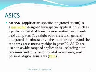
System-Verilog and UVM mini workshop 14 th November 2013. Verification of complex mixed signal ASICs. T . Hemperek. Moore's law in HEP. Switch to big “D”, little “A”. Same pattern for HEP. Verification. Verification plan Simulation Assertion based verification Formal verification

E N D
System-Verilog and UVM mini workshop 14thNovember 2013 Verification of complex mixed signal ASICs T. Hemperek
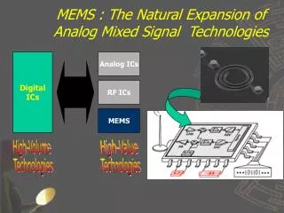
Switch to big “D”, little “A” Same pattern for HEP
Verification • Verification plan • Simulation • Assertion based verification • Formal verification • Mixed signal verification • FE-I4
Assertions based verification A pattern describes a proven solution to a recurring design problem // A start can only occur after a grant for an active requestassert property (@(posedgeclk) disable iff (~rst_n)req[*1:8] ##0 grant ##1 req |-> start);
Formal verification // SystemVerilogAssertion propertyp_arb; @(posedgeclk) req|=> ##[0:2] gnt; endproperty assertproperty (p_arb);
Accuracy versus performance Source: Cadence Design Systems
FE-I4 Top View ANALOG ARRAY (digital part) DIGITAL ARRAY END OF COLUMN END OF CHIP COMMAND DECODER PLL PLL REGISTER MEMORY DATA OUTPUT - verilog model - Implementation (rtl/gate)
FE-I4 Verification environment For FE-I4 we heve 4 OVC: - PIX - CMD - REVEIVE - MANUAL
A UVM layer for PyHVL http://www.fivecomputers.com/a-uvm-layer-for-pyhvl.html